Tortoise Machine Installation...


Rick,


Mounting these things is one thing, wiring them is another. I have looked at a number of pictures of their wiring (all of which seem to include multiple machines, extra bits of electronics, lights and other stuff that just confuses me. I have not been able to locate a single diagram that shows the simplest most basic wiring of these things.

I am assuming that the tortoise gets its power from the track power/main Bus with one wire attached to it at either end terminal. If that is the case, then all I should need to do is run two more wires, from the tortoise, to my toggle switch so it will work. Is that about it?

You would be much better off wiring them to an accessory bus than to track power. If you short (I'm assuming DCC here) you lose the ability to reset turnout with out physically moving the train and clearing the short first.


Tortoise wiring.png
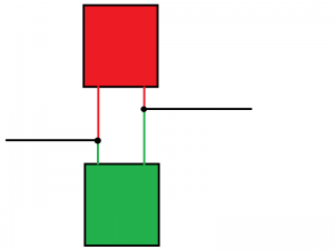
Here is a pretty straight forward wiring diagram for the tortoise machines. this will throw the turnout back and forth and give you an LED indication of which what the turnout is thrown. You will need a Double Pole, Double Throw (no center off) switch (DPDT) and two LED's of you color choice (I use orange for mainlines and red for spurs), a power source and tortoise. The outer two pins of the switch machine control the motor. When the motor is stalled it acts as a resistor for the LED's so you don't need one in line with the circuit. This is the simplest method of showing position indication. if you have do not need to show position indication just don't put the LED's in line with the circuit. The LED's will go dim when the machine is moving but will brighten back up once it has stalled (thrown completely).

The DPDT has the outside terminals wired together in an X pattern (lower left connected to upper right, Upper Left connected to lower right). The center two poles connect to the outside pins of the switch machine.

While you can buy edge connectors to hook up to the tortoises, I don't bother with them since it is only two wires connected to the machine. I pre-solder about 10ft of wire (I use 1 pair of wires from network cable) to the machine and then install it in its desired location. No soldering under the layout.

I use this method for all my non-mainline turnouts on the layout. the mainline turnouts are connected to stationary decoders so the dispatcher as well as the local operator have control of the turnouts.
 
This is the fifth time I have tried to reply so hopefully this time it will work. Thanks for the diagram and simple to follow instructions for the wiring. This is perfect for me.
 
Hi,

Tam Valley Depot has a couple of servo based solutions:

http://www.tamvalleydepot.com/products/microsingletservodecoder.html

http://www.tamvalleydepot.com/products/switchwrightmachine.html

But you can get the Tortoise with decoder for little less money and, IMO, an easier install.

http://www.modeltrainstuff.com/Circuitron-Smail-p/cir-800-6200.htm

Frederick

There is a more cost-effective Tam Valley Depot solution: the Quad-Pic Servo DCC Accesory Decoder.

It costs $39.95 and controls 4 servos (which cost less than $2 each). That's $12 per turnout, less than half the cost of the Tortoise with decoder. Tortoises are great, but if your budget is an issue, the servo approach saves money.

- Jeff
 
Jeff,

Budget isn't an issue as such, just so long as what is gotten works and is reliable. Obviously, if the servo's work and are reliable, then they are a much better option than a conventional switch machine in my opinion.

Anything I did buy would be bought through Klein's though as they seem to be the cheapest and most reliable place around from my experience. In order of cost though (through Klein's) the most expensive option is the DCC Tortoise (smail I think it is called) at around $29.99 per machine, followed by the DCC Concepts Digital at $22.95 per machine followed by the Servo's. The servo option, even with a separate DC power source comes in much less expensive.

Bottom line, if I were to install switch machines for every turnout I would be looking at $1000 plus for the smails, around $750 plus for the DCC Concepts and around $125 for the servo's plus dc power supply, not including tax and shipping.

I guess on the financial front it really should be a no brainer huh :)
 
Last edited by a moderator:
There is a more cost-effective Tam Valley Depot solution: the Quad-Pic Servo DCC Accesory Decoder.

It costs $39.95 and controls 4 servos (which cost less than $2 each). That's $12 per turnout, less than half the cost of the Tortoise with decoder. Tortoises are great, but if your budget is an issue, the servo approach saves money.

- Jeff

I didn't mention that because Tam Valley says it is not recommended for new users.

The Tam Valley servos with mount and switch are listed at $16.

I got the impression that Wombat was not a fan of hot gluing servos under his layout.

Frederick
 
Frederick,

It isn't that I am not a "fan of hot gluing" I just haven't had the need to do it before. The photo's that Jeff posted show an obvious tube across the top of the layout. What I was saying was, I wish that wasn't as obvious and the connections for servo use could be less obvious.

If servo's can be installed similar to other machines (out of sight) with the components that connect the machine/servo to the draw bar then I wouldn't have a problem using hot glue or any other method for attaching the servo to the under side of the layout.

With that being said, and after what Renegade posted (the diagram and explanation of the wiring), I am inclined to go the Tortoise route with a DC power source for simplicity sake more than anything.
 
Last edited by a moderator:
I didn't mention that because Tam Valley says it is not recommended for new users.

The Tam Valley servos with mount and switch are listed at $16.

I got the impression that Wombat was not a fan of hot gluing servos under his layout.

Frederick

Good points, Frederick. Servos are not for everyone, but since Tony asked for alternatives, I was happy to offer my experience.

Personally, I did not purchase my servos from Tam Valley. Any 9-gram class servos will work, and they are readily available from other sources for less than $2 each with free shipping. And the hot glue installation method is easy and cheap. Quite a savings!

- Jeff
 
Last edited by a moderator:
Frederick,

It isn't that I am not a "fan of hot gluing" I just haven't had the need to do it before. The photo's that Jeff posted show an obvious tube across the top of the layout. What I was saying was, I wish that wasn't as obvious and the connections for servo use could be less obvious.

If servo's can be installed similar to other machines (out of sight) with the components that connect the machine/servo to the draw bar then I wouldn't have a problem using hot glue or any other method for attaching the servo to the under side of the layout.

With that being said, and after what Renegade posted (the diagram and explanation of the wiring), I am inclined to go the Tortoise route with a DC power source for simplicity sake more than anything.

My bad - I misunderstood.

The Tam Valley servo with mount and switch, that I mentioned, is a more "Tortoise-like" in regards to installation.

The type of installation with a wire/brass tube setup works well and once you paint them and ballast the track they are not very noticeable BUT they are more noticeable then a standard "Tortoise-like" install.

Frederick
 
Good points, Frederick. Servos are not for everyone, but since Tony asked for alternatives, I was happy to offer my experience.

Personally, I did not purchase my servos from Tam Valley. Any 9-gram class servos will work, and they are readily available from other sources for less than $2 each with free shipping. And the hot glue installation method is easy and cheap. Quite a savings!

- Jeff

Are you powering your turnout frogs?

If so, since the servo picture posted does not show any associated switch, how are you doing it?


One thing I ran into with some very cheap servos for another project was that they would not respond to an large abrupt change in pulse width, say from 1.0 mS to 2.0 mS (0 to 180 degrees).

They worked fine in a more typical RC setup where the pulse width "ramped" from one value to another.

It was curious.

Frederick
 
Frederick,

No problem mate, no offence taken, and no I'm not powering my frogs as I am using Peco Insulfrog turnouts. While they may not be as "good" as the electrofrog turnouts, there is less work involved (wiring wise) with their installation. I used the insulfrogs on my shed layout (n scale) and only ensured that I had power to the rails immediately before and after each turnout. That seemed to work fairly well although there was the "occasional" stutter when an engine passed over them.
 
Okay so I have just ordered the following items to use as practice:

1. [FONT=&amp]Circuitron 800-6000 The Tortoise(TM) Switch Machine [/FONT]
2. 25' solid 20 gauge wire (Red)
3. 25' solid 20 gauge wire (Black)
4. [FONT=&amp]Circuitron 800-6190 Drilling Template for Tortoise[/FONT]
5. [FONT=&amp]A.E. Corporation MTS-8 DPDT On-On Mini Toggle Switch[/FONT]
6. [FONT=&amp]Tomar HO 6075 Axial LEDs, Green (6)

Hopefully that is all I need to start with. The only concern I have is with the LED's, I trust that any LED will do the job.[/FONT]

That should be fine for starters.

How many turnouts will you need for your layout?

Depending on that number you can save some money buying from other sites.

For example my "go to" site for electronics sells ten 5mm (that's the diameter) Green LEDs for $1.50.

Frederick
 
Frederick,

Thanks, that is reassuring.

If I do all of my turnouts I will 34 in all. At this stage I am only looking at doing the furthest turnouts. If installing these are as easy as renegade has made it look, then I will do the remainder.

To be honest, I just bought the Tomar LED's so I had everything together and didn't have to wait for something to turn up. When I do this in "bulk" I will be buying my LED's and probably wire from another source. On that, do you recommend 5 mm or 3 mm LED's? I have no idea what size the ones are I bought.
 
Hi,

I don't see any size mentioned on those Tomar items but it says that are for signal heads.

If they mean HO I'm guessing they are quite small - maybe 1.5 mm.

For panel displays you might prefer the larger 5 mm ones.

Frederick
 
Renegade (or anyone)

I am a little confused by the LED wiring. Can you please explain what you mean by the part highlighted in green:

Tortoise%20wiring%20A_zpsgmyw1qyc.png


Everything else is very clear to me and sorry for the extra question.
 
Renegade (or anyone)

I am a little confused by the LED wiring. Can you please explain what you mean by the part highlighted in green:

Tortoise%20wiring%20A_zpsgmyw1qyc.png


Everything else is very clear to me and sorry for the extra question.

Hi,

LED have an Anode and a Cathode connection.

Often the LED is manufactured with one lead being longer then the other to help identify which lead is which.

For this setup it doesn't matter which is which AS LONG as you connect one LED in the reverse of the other.

Thus the "long leg to short leg" remark.

The long lead of LED #1 would be wired to the short lead of LED #2.

The long lead of LED #2 would be wired to the short lead of LED #1.

Frederick
 
Frederick,

Ah okay, so would this be right?

LED%20Wiring_zpsxelme6qm.png

The LED wiring is not correct.

In my previous post I stated...

The long lead of LED #1 would be wired to the short lead of LED #2.

The long lead of LED #2 would be wired to the short lead of LED #1.


You have them shown in SERIES in your diagram.

They need to be in PARALLEL but one would be "reversed" with respect to the other.

My diagram is not as fancy as yours but I hope it is adequate and makes things clear.

Frederick
 

Attachments

  • Back-to-Back LEDs.png
    Back-to-Back LEDs.png
    8.6 KB · Views: 201
Tony if you have them use a single bi-polar LED. (red/green)
Simply wire in line and if it's not showing the correct color reverse it.


Back
Top