garage layout progress (part 2)


tankist

Active Member
Left the electronics alone for this evening and focused on bridges.

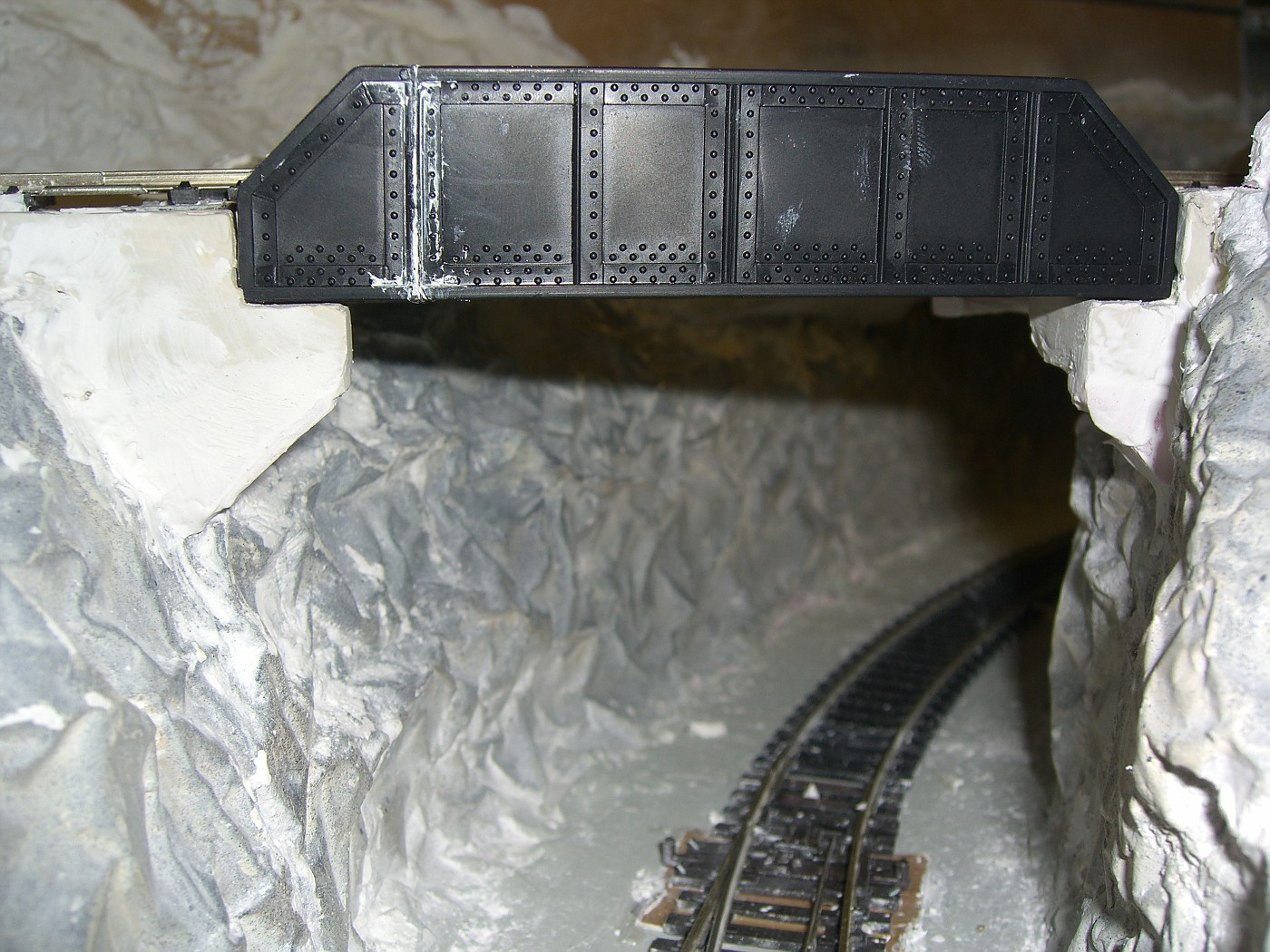
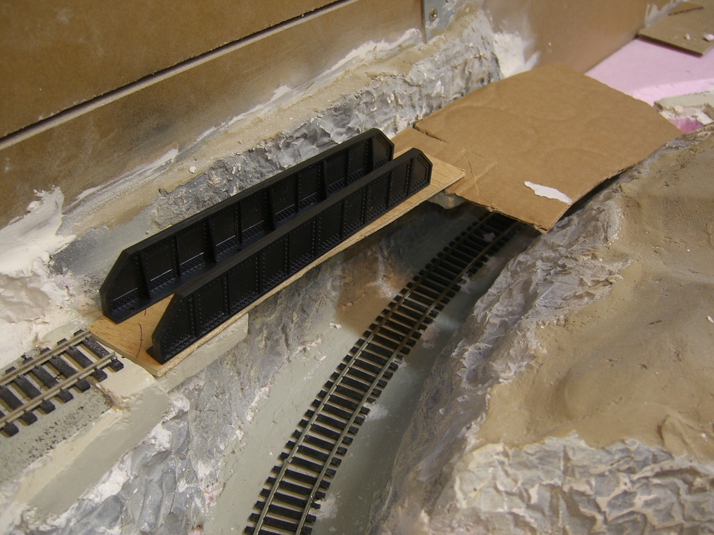
new removable span from the descent bridge.

CIMG1382-vi.jpg


the plywood is thin and flexible so i glued in a square dowel on the underside. the plastic side "panels" were to long so i cut out 4 sections from the middle and super-glued the ends. rail is not permanently attached.

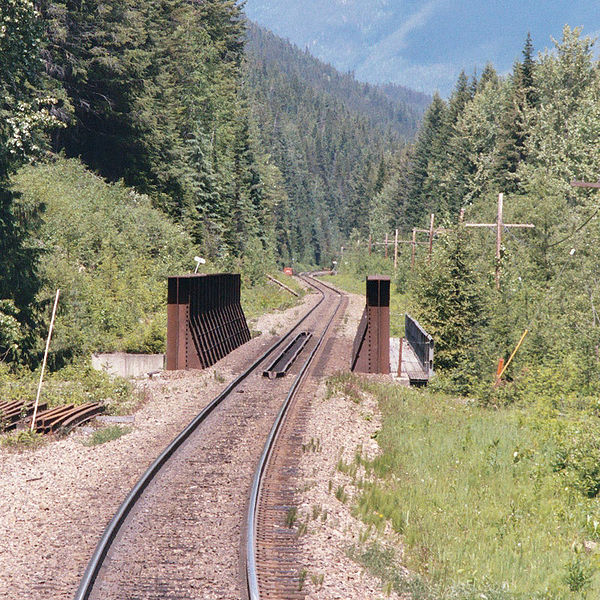
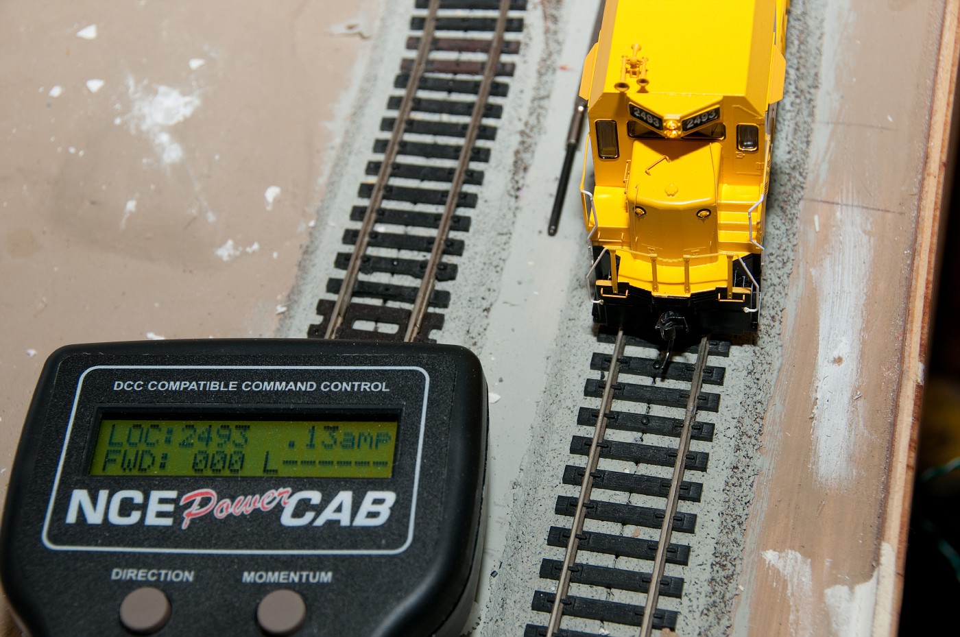
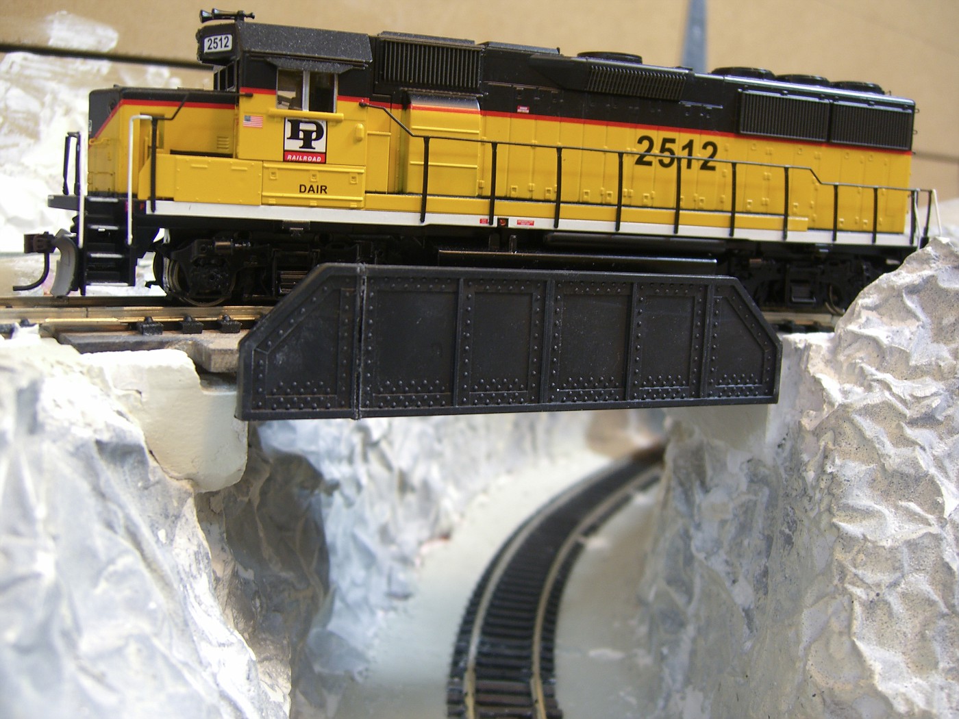
DAIR #2512 approaching.

CIMG1392-vi.jpg


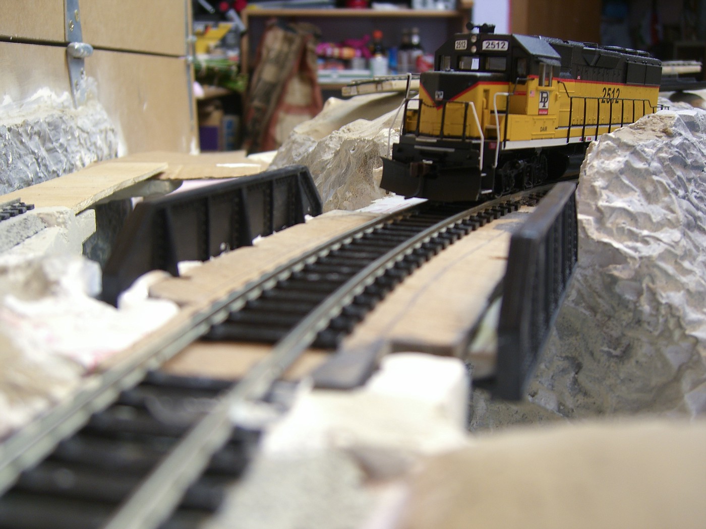
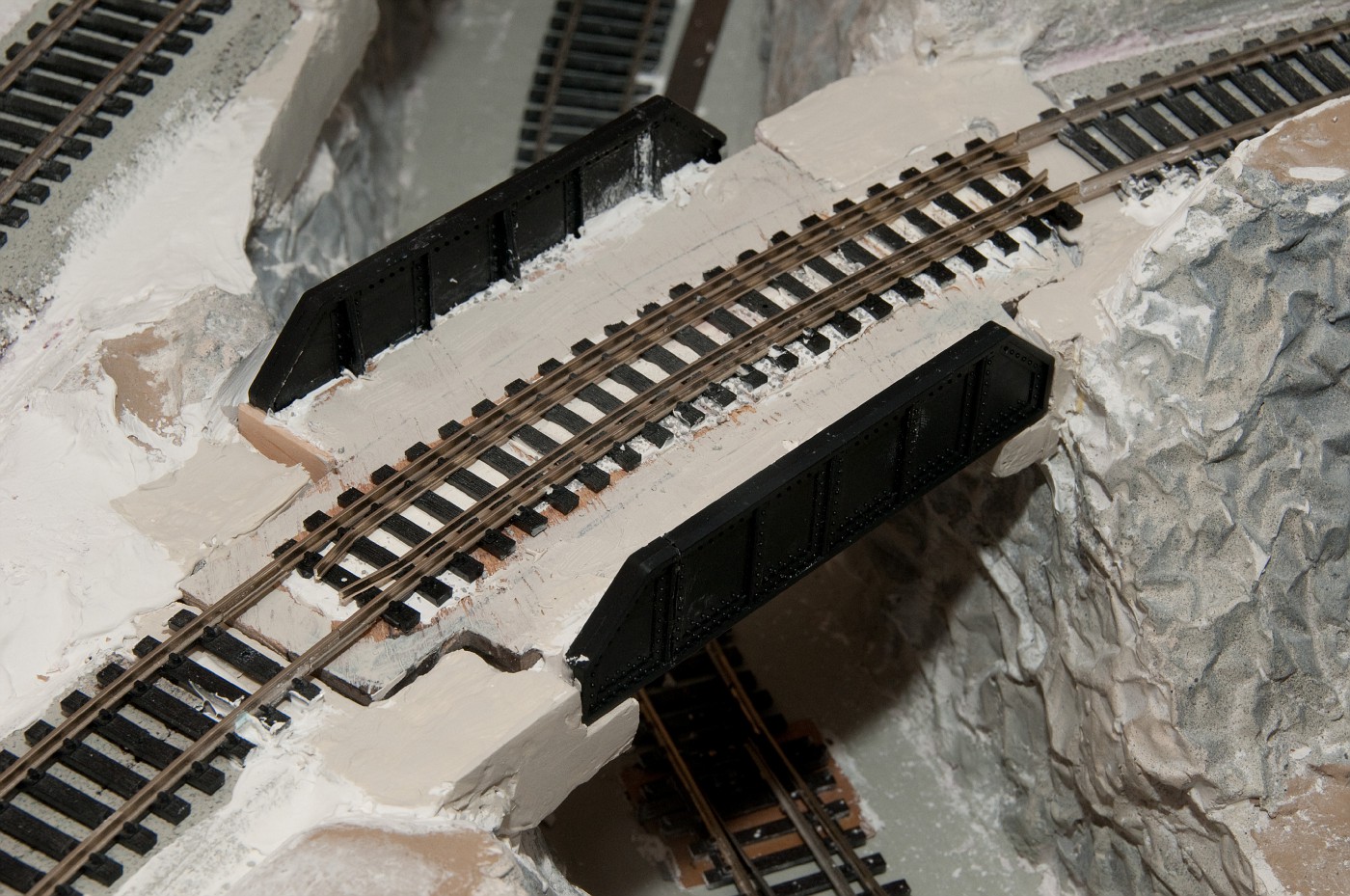
side view. it actually looks like a bridge now

CIMG1390-vi.jpg


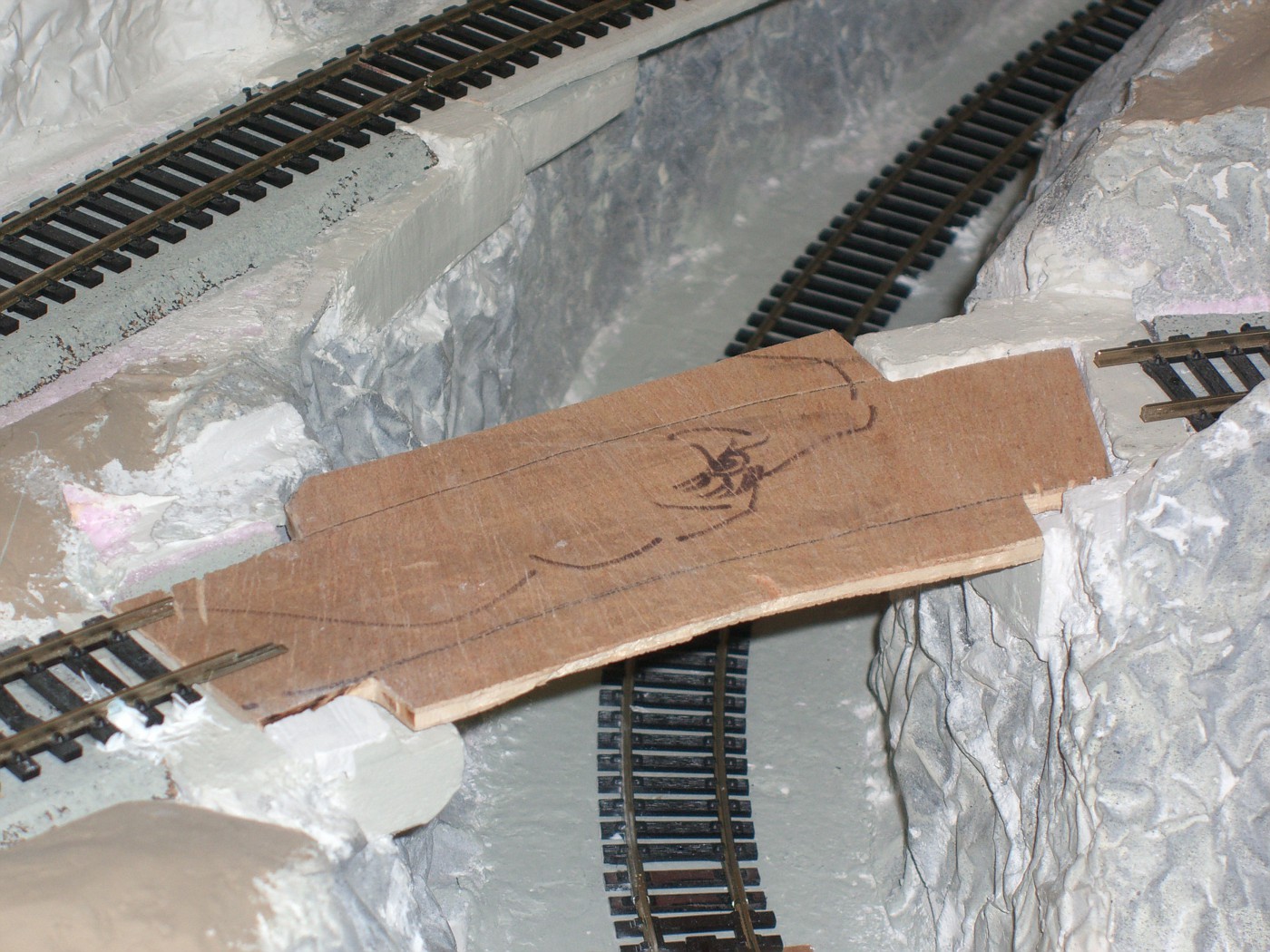
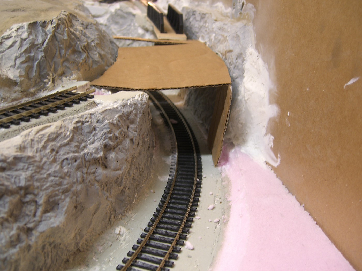
while glue dried i started prototyping the culvert under the climb bridge from cardboard. no worries, there will be enough clearance when its done (some rock "blasting" will be required).

CIMG1385-vi.jpg


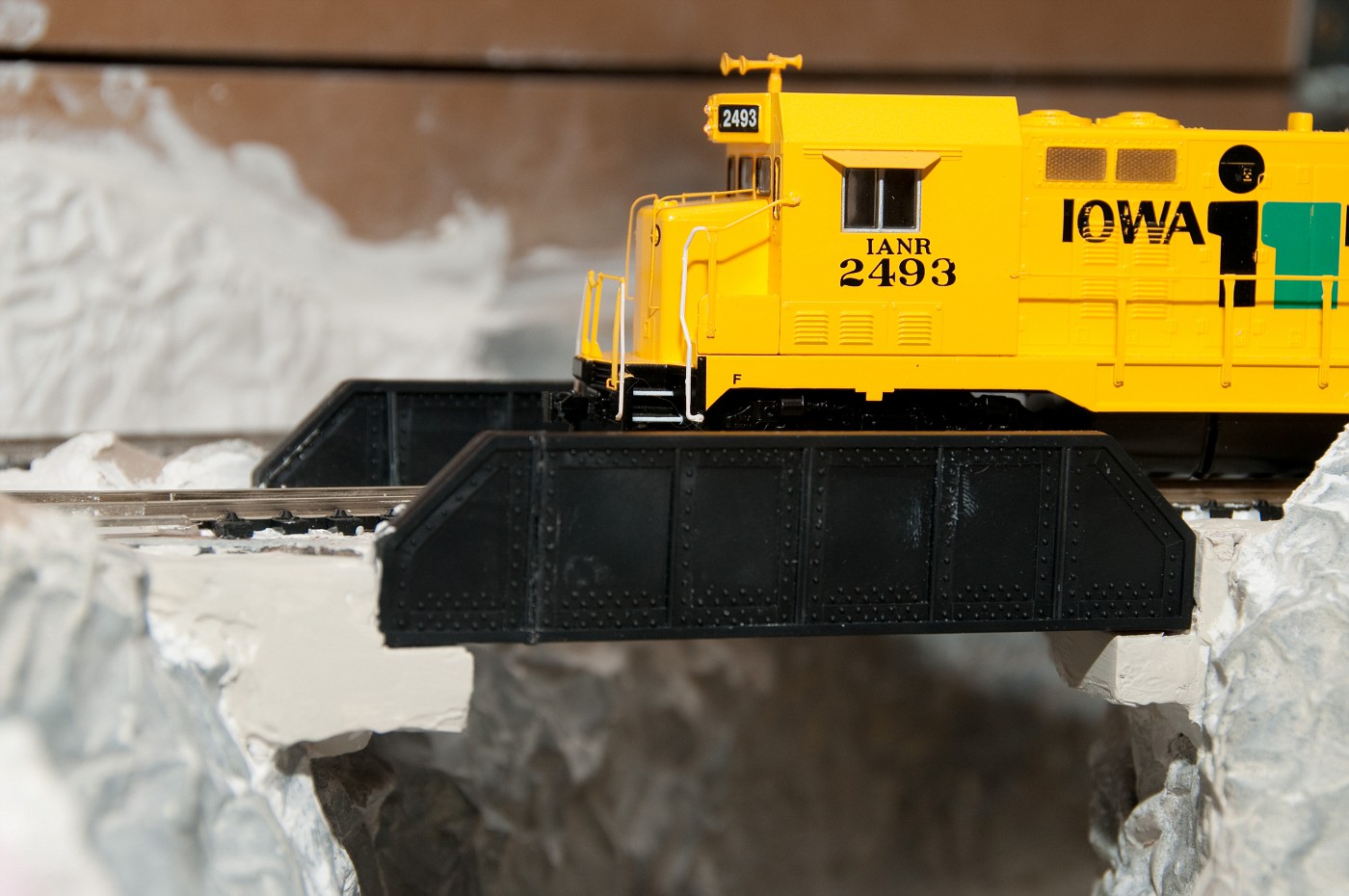
new shortened span with the plastic sides.

CIMG1384-vi.jpg
 
Last edited by a moderator:
Hi Anton,
What your doing looks pretty interesting, I never tried building a RR using foam as I can see it requires the opposite thinking I'm used too to get the excavations or the elevations, depending on how you want to look at it.

The one thing I did notice in the 2nd and most apparent in the 3rd shot is that your Plate girder bridge sides should sit on top of the board you have spanning the lower line to appear as though the Plate Girder Bridge is supporting the track. I'm not sure of how the Plate Girder sides attach but it seems that all you'd have to do is to swap positions and put them on top of the board to give a more prototypical height to them as the rail and ties always sits directly on them, even if it is just fastened to the span board you can always ballast a bit to cover the board or just paint it a medium to dark Grey color.

Also, do you have any passing siding figured in on the track plan as well as sidings for some types of industries here and there? That will provide a lot more realism and operation.

I do see that in your last photo it looks like you are intending to place the plate girders on top of the span board and you can see the more prototypical height to the Plate Girder sides.

Looking forward to seeing future progress!
 
Last edited by a moderator:
David,
thanks for your comment. when i started i considered going with cardboard lattice but settled on foam and can't be happier. i really enjoyed carving it :)
the entire progress from day one is documented here:
http://public.fotki.com/tankist/ho-1/progress/

here is the 2 areas of main module i'm planning industries on.

DSC_8892-vi.jpg


.
DSC_8898-vi.jpg


as far as the bridge, i did notice that girder is usualy underneath the tracks. but i have minimal cleance so i decided to go for something like shown below. the picture of the particular bridge i used as reference to copy is at home (additional concrete supports at girder ends are planned.)


600px-PlateGirderBridgeUType.jpg


in my case it needed to be even wider since the track on top is curved. i was thinking to screw it on top of plywood plank but then the plywood sides would be visible and as far as i can tell the there is never anything below the girders aside from end supports.


edit:
another image. or do you think the sides shown here are concrete?
_wsb_582x490_1310-02A.jpg


3736742905_357b595b6b.jpg
 
Last edited by a moderator:
Hi Anton, [Was hoping you might be the Anton I met locally but I see your in Chicago not Ca.]

Your welcome to my comments, just thought I toss out a little suggestion and see you've
realized it too and given some thought to it. In modeling we are constrainged to do a number of less than prototypical things due to various limitations and structural materials to work with unless we are good at working with Brass and making all the solider joints along with the expense, engineering figuring and time outlay.

So while the plywood would show below the PG bridge you can use a bit of modelers license and add a plastic [L] girder along the edge to make it look like an additional stiffner to carry the weight of the big Diesel Loco's and heavy cars your going to be transporting over the bridge. Most people wouldn't even notice it as when glued on under it who's to say just how deep the lower framwork goes anyway? Paint or stain the underside of the board a dark color and No one will even notice it and you might even be able to raise the whole thing a bit too?

Now if you want to really get tricky you can actually have the PG in a curved form and that is has been done too and I have an actual picture, off the web, of just such a bridge being constructed in a large shop and for RR use too!


I see by your top two pictures you do have sidings and spurs for industries which is good. Also it appears that your layout is divided into two sections? I tried to load your Fotiki pics but my land line fee is way to slow.

It looks like your well under way which is great! Oh, the picture of the actual rail line going through the cut is reall fantastic. I was looking at the cross type of things on the Right side and was wondering what they were until I noticed in the edge I could see a phone line canging down and realized they were telegraph poles. At first I thought they were too spindly looking to be a type of telegraph pole.

Something I also noticed that seemed odd is the blunt lead in on the center gard rails in the track going across the PGB and how much room between them and the actual rails.
I always thought there was just a small space for the wheel flanges to ride in to prevent derailments from taking place? These guard almost seem to poromote it with so much room?

Talk with you later.
 
Anton, the bridge in your first picture is concrete all the way, with the girder sections made from reinforced concrete instead of steel. It's an unusual and old stlye of concrete bridge construction, and it appears to have been added on to several times over the years. It also appears from the demolition work on the left side of the bridge that it's in the process of being replaced.

The second picture is a steel girder bridge with a ballasted deck. The ballasted deck raised it above the usual level of the top of the girders, and subsequent track work has probably raised it even higher.

What looks really off is the picture with the side view of the 2512 on the bridge. The girders should extend all the way to the abutments, with the girders sitting on bridge shoes, like the bridge with the METRA engine. All the strength in a short girder bridge comes from the girders supporting the bridge underframe, so the girders would always go all the way back to the abutment.
 
Thanks Jim, (forgot to add - your comments are always appreciated)
agreed on the abutment, but thats was the state of things as of a week ago :)

today:

concrete supports added. still working on that, as they probably need to be arched

DSC_3378-vi.jpg


some paint, check rail (right?) installed

DSC_3384-vi.jpg


what do you think?
 
Last edited by a moderator:
thank you for the kind comment. however i think i still have room to grow in order get to the 'amazing' grade, i'm new to this as well :)
 
Anton, you're more than welcome. I hate to seem like I'm harping on you, but bridges are just one of those things that make or break the look of a layout.

Those rails are properly called guard rails in the US, although I think check rails is used in the UK.

The bridge looks better with the supports out further but they wouldn't extend the supports out in the air like that for no reason. Do you have the room to extend the supports down to track level, like a retaining wall? It looks pretty tight, but I'm thinking of angling it up from the closest clearance you can get on the track, up to the abutments. The retaining walls would be a good backstory why the girder bridge is so short. I don't know if you can still fit them in, but a set of bridge shoes, like the ones at http://www.walthers.com/exec/productinfo/255-80034, would really improve the look of the girders sitting on the abutments.
 
Jim thanks! actually "harping" is very good - you bring excellent points. i'm obviously don't know as much about bridge construction.

bridge shoes are very good idea to and i will try to make something about them

now i see i should have extended that girder. but for some reason when i though about it last week it somehow made sense to keep the girders equal lenght and right in front each other... should have extended it bit closer so the supports would be more or less equal. i guess i will revisit this area later.

CIMG1399-vi.jpg
 
built a consentration board for turnout position detection microswitches and started soldering leads (i have two for each turnout creatinga DPDT). good thing i decided to double-check if my wiring was conforming to color code i set. the very first turnout i test - nothing. no buzz on either NO or NC lead of one of the switches (the other tested out fine). so i had a fun task of getting the machine out as everything is buried deep at this point and sealed so not to let future ballast in. that's with already completed track work - not fun.

sure enough the micro-switch is shot :mad: clicking but not connecting anything in any position.
ended up un-soldering and cutting everything from it, breaking it off, installing new one all while dealing with trackwork trying not to disturb it to much. which in this area is near impossible as there are 3 of them inter-meshed. good thing i decided to leave wire slack...


2 hours, coule cigarettes (i rarely smoke) and one beer later, everything closed up and turnout #1 is reporting position properly. but this is one frustrating evening. i sure hope that chineese microswitches have higher failure ratio then 1 to 16 ...


PS broke the switch casing open and examined contacts inside. no electrical connection. MFers!!! :mad:
 
that was one piece of a weekend.

Saturday
after I burned by the DOA micro-switch i verified all other turnout position detectors. all checked out fine apart from one instance of miss-wiring. soldered all 48 leads into quick disconnect concentration board (rectifying the one erroneous switch making eight consistent 6 pin connectors.

overview. instead of bunch of wires thats what sticking from underneath the table now
DSC_3477-vi.jpg


8x6 connectors
DSC_3478-vi.jpg


other side. not industrial grade job but it works.
DSC_3480-vi.jpg


Sunday
worked on the other side of quick disconnect board. in the future, when it comes to that i will be building different board to feed the turnout position to PC. for now it is wired as polarity reverserse DPDT harness. I didn't break the pin header strips into indivdual sections so to preserve strength. connected to the quick disconnect board is thin board with 8 connectors to the LED indicators and limiting resistors for these LEDs. white/brown wire pair is power input.

DSC_3482-vi.jpg


connector for bi color LEDs with limiting resistors
DSC_3483-vi.jpg


polarity reversing DPDT connections in progress (4 leftmost done). looks horrible but so far no shorts.
DSC_3484-vi.jpg


all the signals on control panel can be powered from track - DCC. on the right power is the input header. 4 shottky diodes make a rectifying bridge + small capacitor to smooth the resulting voltage. the quick disconnect harness will be powered from here. 7 pairs of connectors are for constant color diodes. more LED limiting resistors are on the underside
DSC_3485-vi.jpg


both thin boards will be located on the front side of control panel housing
DSC_3498-vi.jpg
 
Testing.
connected power to track and placed engine to verify my creation doesn't get the powercub into short protection mode. some glowing LEDS can be seen

DSC_3486-vi.jpg


power draw with the engine (headlight on)
DSC_3487-vi.jpg


I simply love glowing LEDs. cant wait to seem them all powered and actually indicating positions.
DSC_3492-vi.jpg


BONUS :)

Gathered and "Marinaded" (50/50 glycerin and denatured alcohol solution ) some moss from my back yard. i think its going to make excellent vegitation.

DSC_3494-vi.jpg


small shelf to put away the tiny bottles of paint
DSC_3493-vi.jpg
 
turnout position indication project is complete :D
after troubleshooting and removing one shorted lead and one disconnection, all the circuits are installed into the control panel enclosure and connected. cut and bent aluminum angles to mount the enclosure to the table

view from underneath.

DSC_3507-vi.jpg


the connector
DSC_3506-vi.jpg


applied power and it is Christmas :D :D !!! decided on Green/Green for streight route, Red/green for diverging. it is not really signaling but untill i have full fledged PC controlled signaling system this will do

DSC_3513-vi.jpg


and it even responds to throwing turnouts! crossover is closed (or is it "open" when set to go straight), diverging route selected on the decent line (lower, right most turnout)
DSC_3516-vi.jpg


total power draw (again, plus loco with headlight glowing)
DSC_3515-vi.jpg


half way there, now need to mount and connect the CDUs to actually throw the turnouts.


.
 
Thats a really smart job your doing, foam is brill for working with and if i ever get to build my new railroad it's my material of choice. The electrical wiring job is very impressive.

good work fella
 
Thanks for the update. Looking really good.

btw, how did you get the amp draw indication from your powercab?
 
thanks guys. i'm really really happy that it came together if you can't tell. the only thing i'm kicking myself is for throwing those old 50pin SCSI connection wires. would make simply perfect connector instead of my contraption

Thanks for the update. Looking really good.
btw, how did you get the amp draw indication from your powercab?

looks like somebody didn't read the manual ;)
you get into cab configuration (press program till you get to correct page, 5 times i believe) and this option would be on second screen right after cab address. :)
once done testing, i will probably turn the clock back on. not that i know what to do with fast clock, but the screen looks neater. or maybe i'll get used to amps...

manual? What is that? LOL
I've read it, but never saw that option, I'm still learning how to use it, only had it for a month or so.

I agree, what the heck is the fast clock all about, I probably will never use it either.
 
I agree, what the heck is the fast clock all about, I probably will never use it either.

In model railroading, we compress reality to fit our layouts. A train can travel from one 'town' to another much faster in than in real life. During operating sessions, a lot of work must be done in eight 'hours.' This is where the fast clock comes in. It speeds up the time we have to accomplish our tasks. We may only have two hours to get as much 'work' done as a real railroad would do in eight. So the fast clock would run four times faster than a real clock. Try not to leave anything undone for the next shift. It really hacks them off.


Back
Top