garage layout progress (part 2)


it is almost 4AM...

the 3 solenoid driver circuits are finished and consolidated into 1 device. added additional capacitor to consistently throw paired turnouts (one channel driving 2 coils)

DSC_3517-vi.jpg


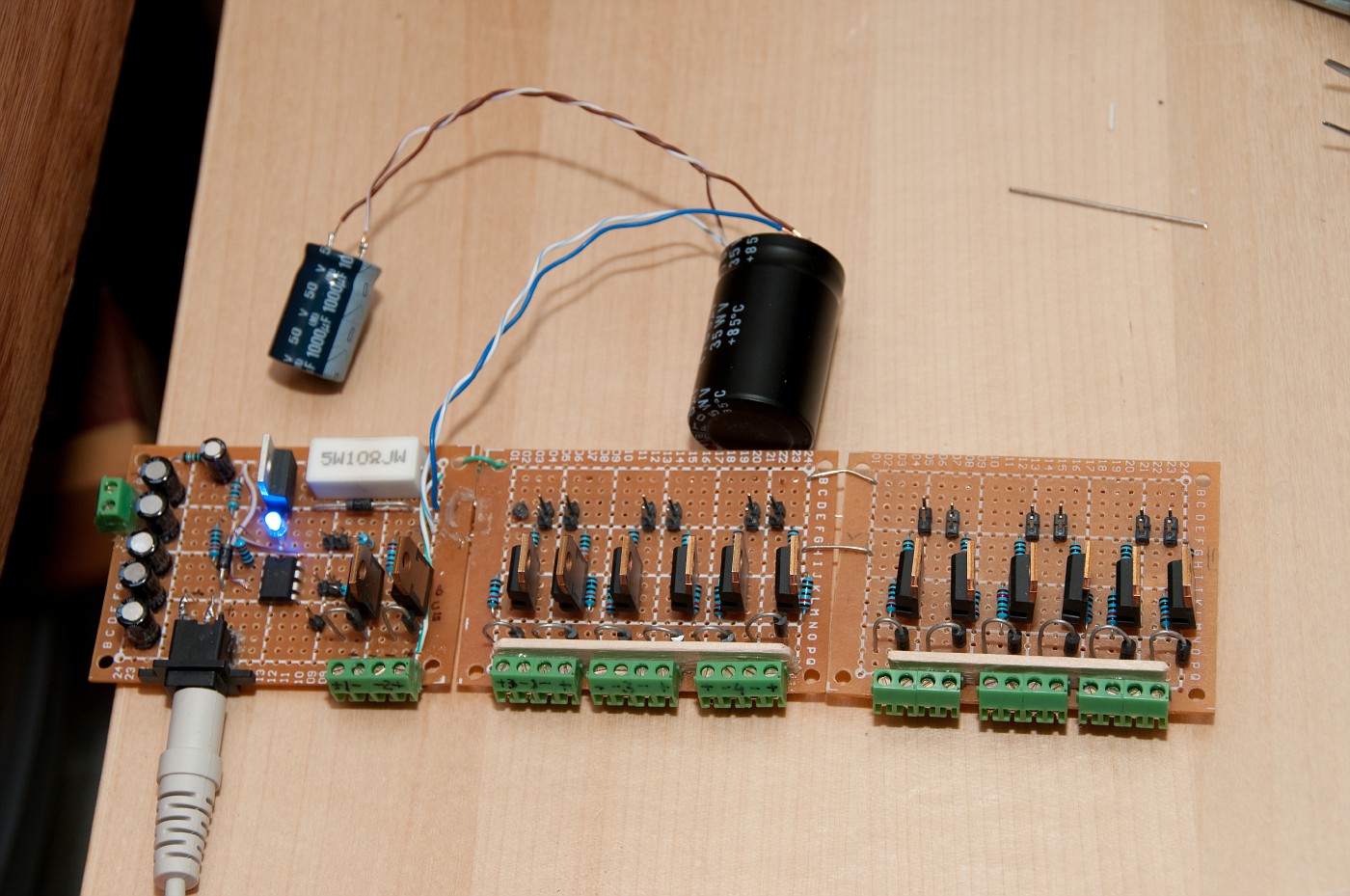
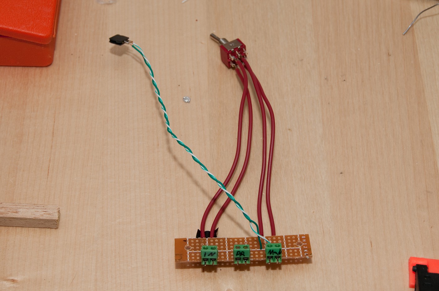
program track circuit. the turnout indication is powered from the "run" side. this way when switch set to "program" there no illumination but the red LED of the powercab base.

DSC_3519-vi.jpg


all came together. and the real surprising thing it all works! :D
little wire management will be done later
DSC_3520-vi.jpg


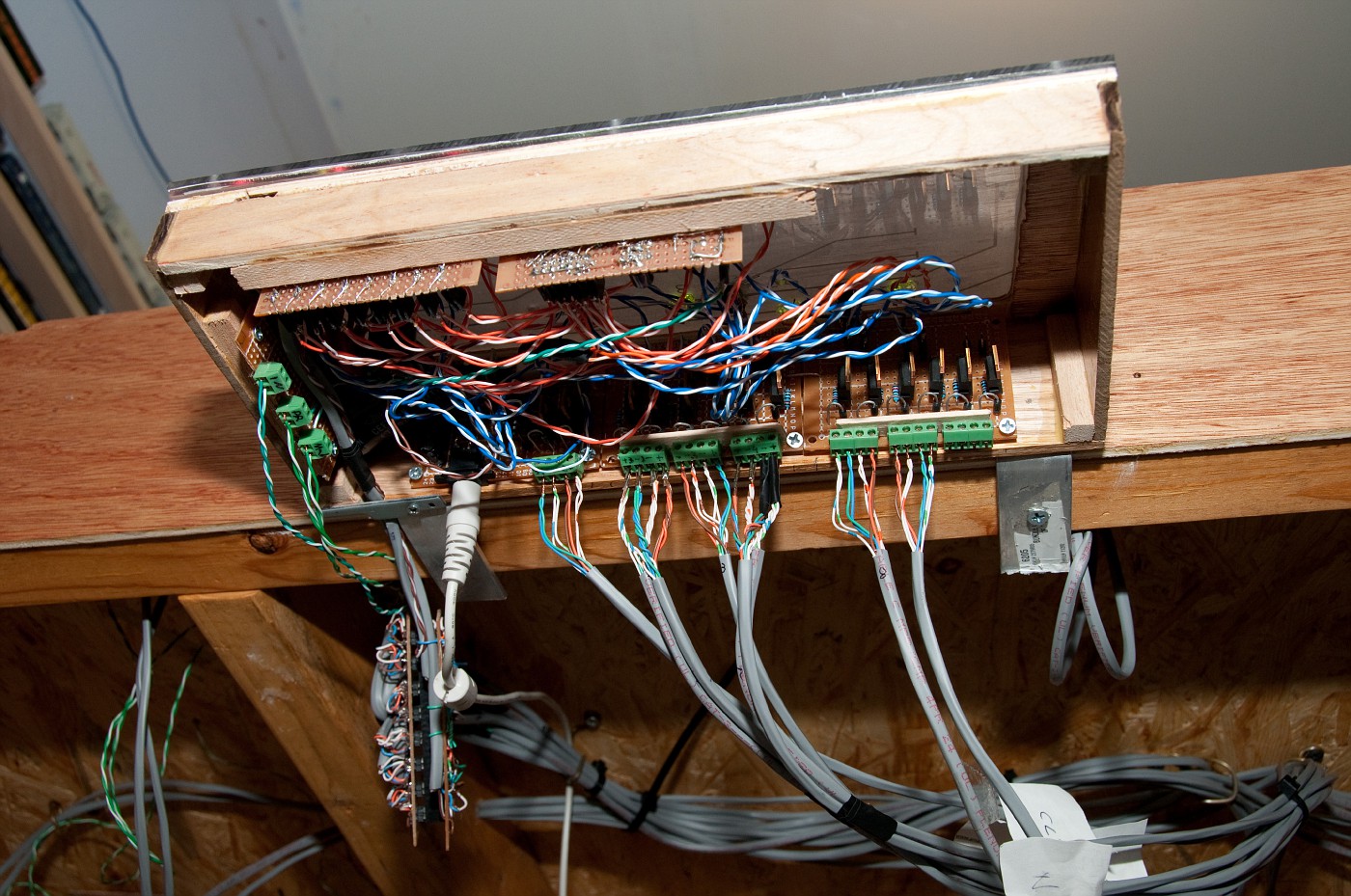
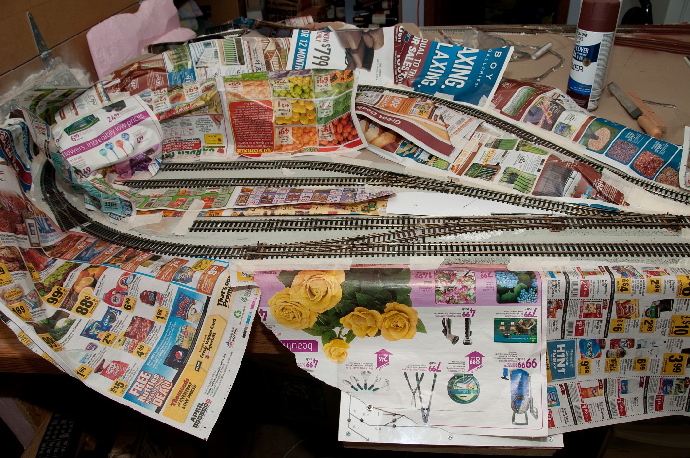
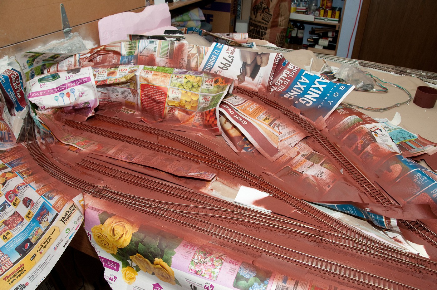
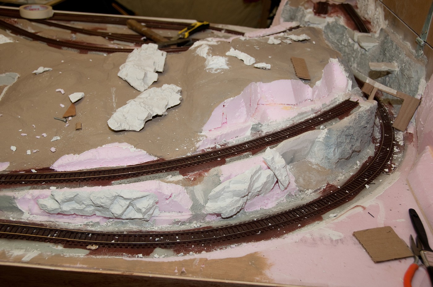
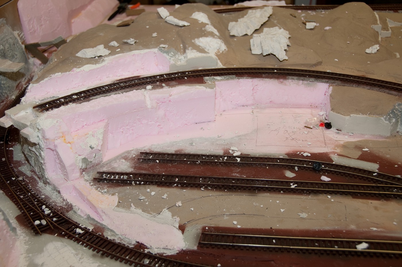
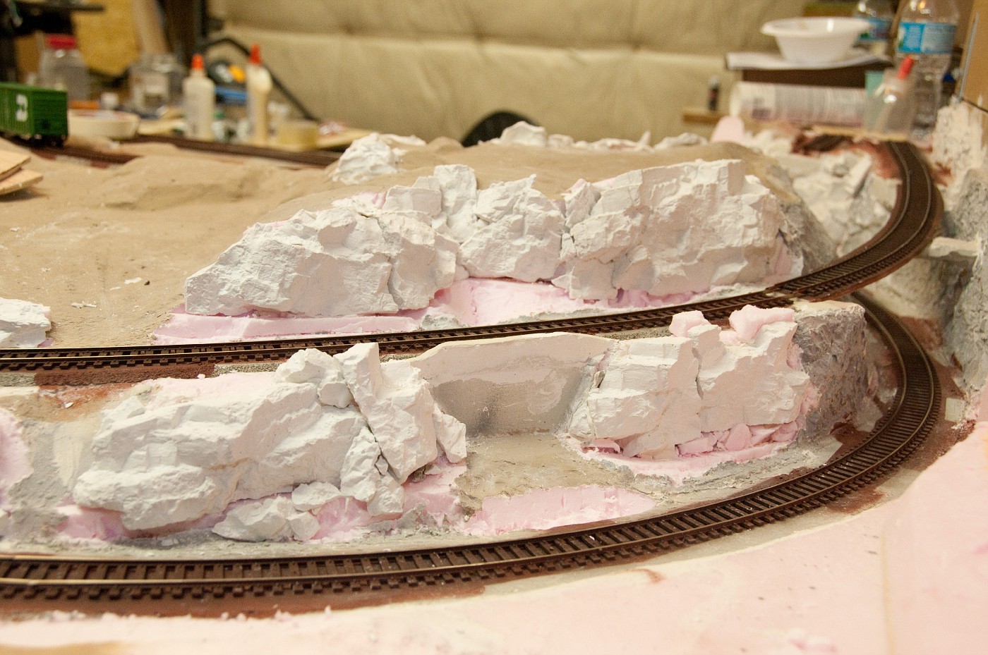
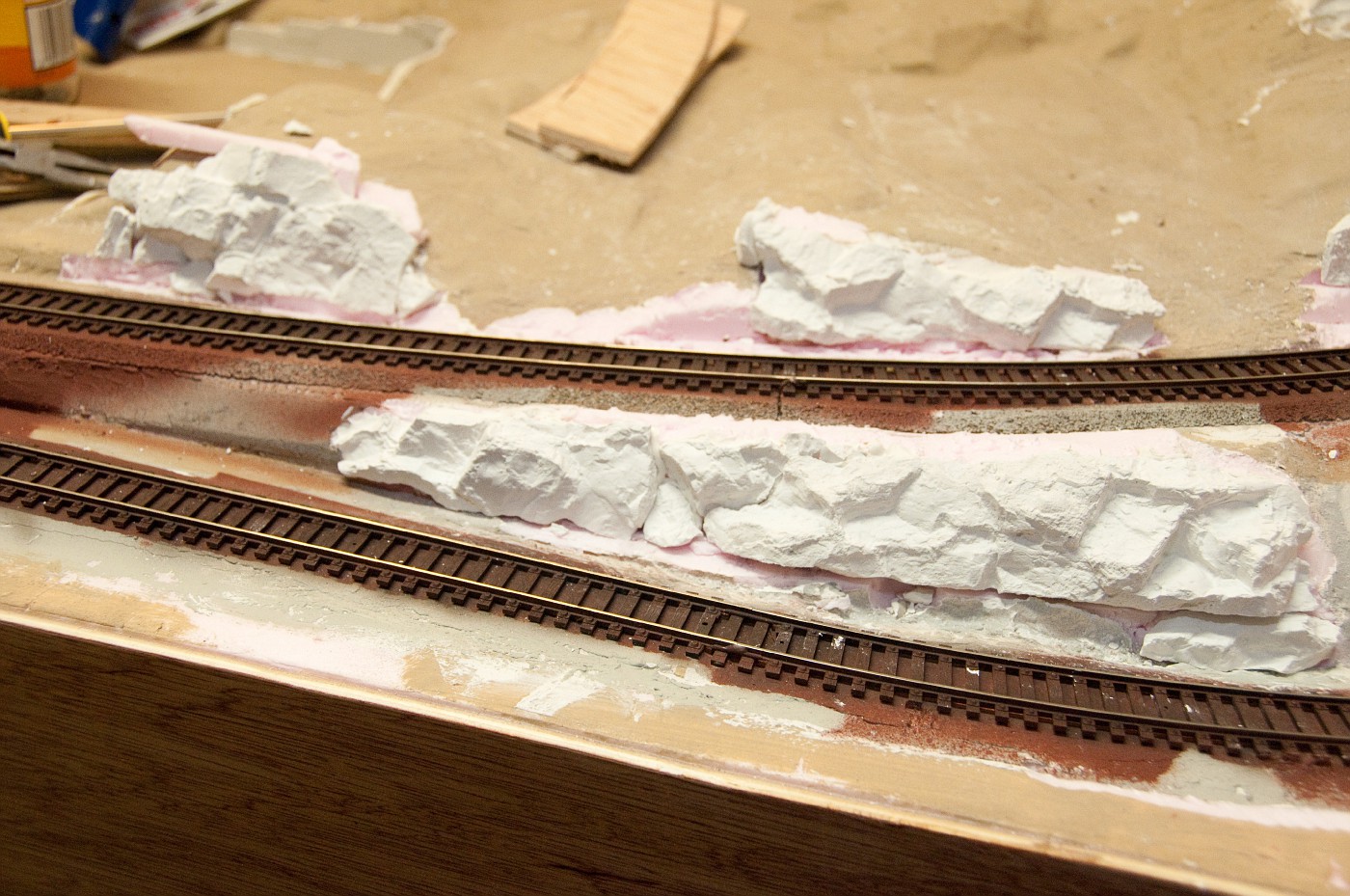
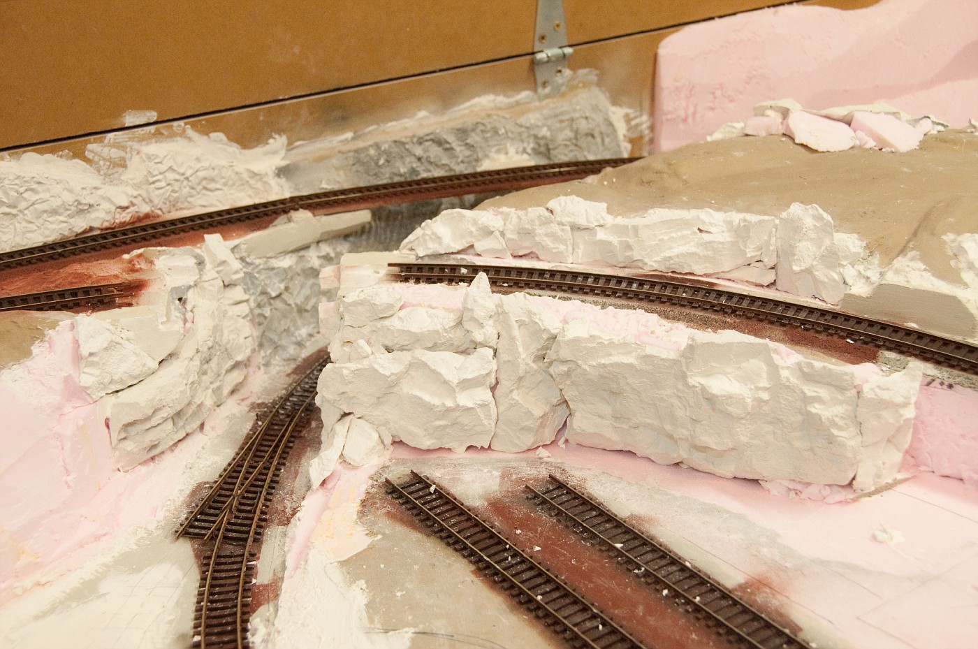
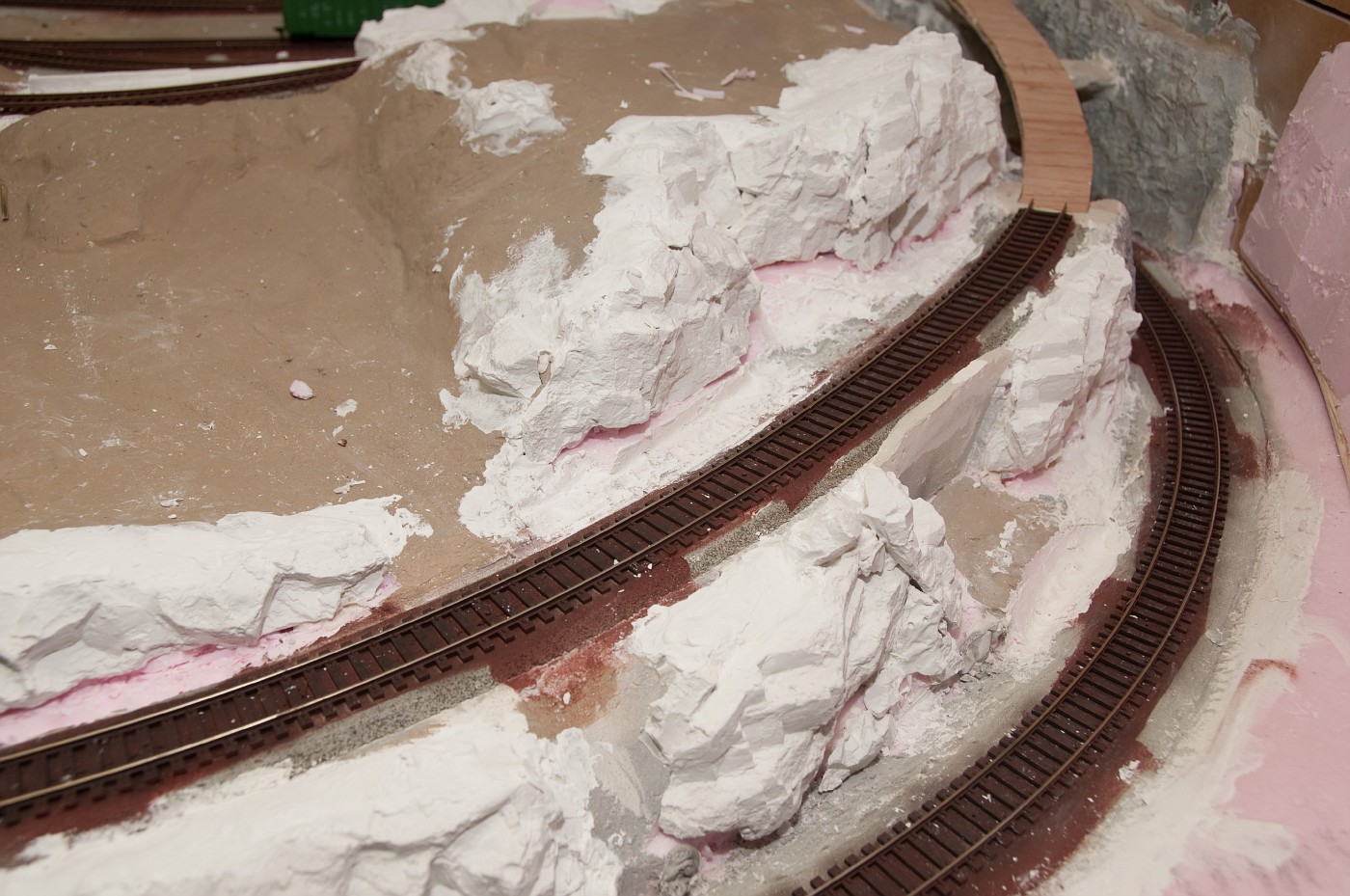
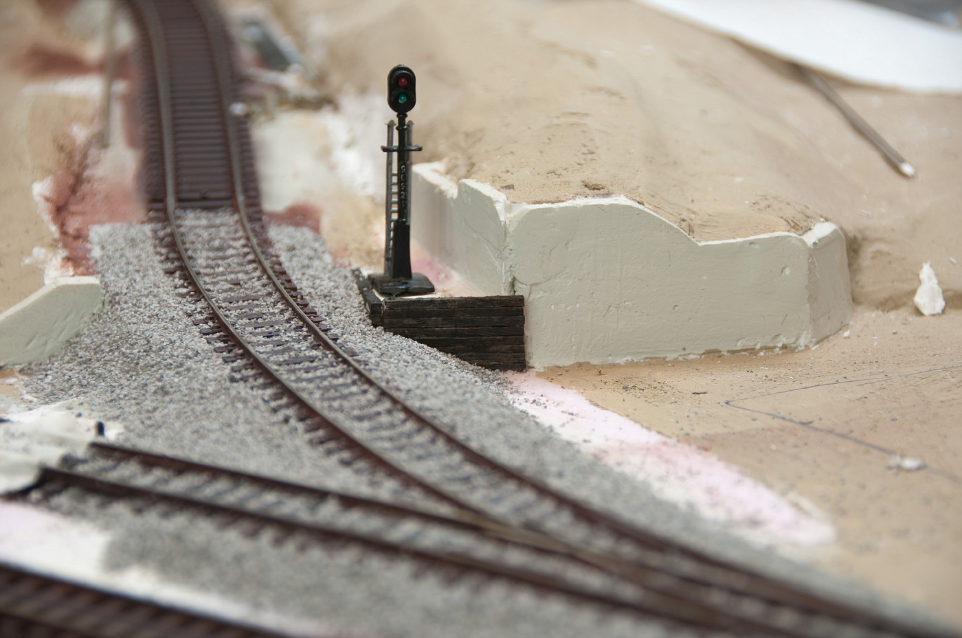
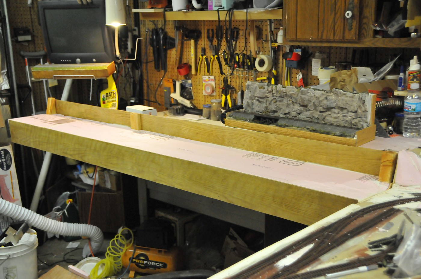
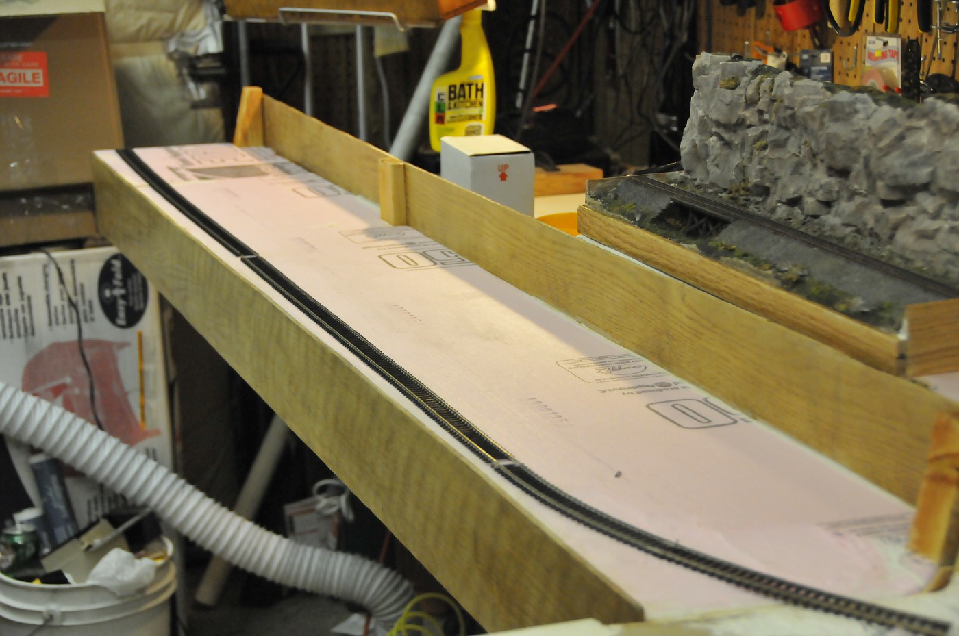
now with electronics out of the way its scenery time
 
Last edited by a moderator:
Anton,

I don't even know what all those electronics do, but it looks like a professional did it.

Working on the MRR at the 4am = Priceless.
I love the weekends.
 
started weathering tracks. tried airbrushing acrylic but just didn't have the patience for 4 layers. decided to try that brown/rusty primer and really like how it turned out. rail is IMO has perfect color or very near (in my lighting conditions), airbrushing ties now should not be a problem.

newspaper world
DSC_3522-vi.jpg


after rusty storm
DSC_3523-vi.jpg


couldn't wait sprinkled bit of ballast, will be vacuuming it up shorlty and painting ties to quench that redish-ness
DSC_3524-vi.jpg
 
the 3 solenoid driver circuits are finished and consolidated into 1 device. added additional capacitor to consistently throw paired turnouts (one channel driving 2 coils)

DSC_3517-vi.jpg
I'm unsure what the circuit actually does. I have used solenoid motors and had one CDU with on,off,on self-centering switches (will be probe and stud) and don't use all them regulators/capacitors/resistors and the IC.

What are they all for?

all came together. and the real surprising thing it all works! :D
little wire management will be done later

DSC_3520-vi.jpg

That looks like Cat5/6 wire. Is this suitable for the current that solonoids use? AFAIK the current is quite high albeit for a short time. Is this ok as I'm soon to be doing the wiring on my new layout and cat5/6 would be ideal if it's capable.

Angie
 
That looks like Cat5/6 wire. Is this suitable for the current that solonoids use? AFAIK the current is quite high albeit for a short time. Is this ok as I'm soon to be doing the wiring on my new layout and cat5/6 would be ideal if it's capable.

Angie.
this is actually a phone wire. same gauge wire but cheaper (used since i had crate of it already). since i'm using 1 cable per machine for total of 4 contacts i paired the wires. but even without it worked just fine. i have old Roco doubleslip with integrated coil drivers, the wires they used there are even of lesser gauge.

I'm unsure what the circuit actually does. I have used solenoid motors and had one CDU with on,off,on self-centering switches (will be probe and stud) and don't use all them regulators/capacitors/resistors and the IC.

What are they all for?
if you had one CDU then you had to use Capacitors - capacitor discharge unit kinda has to have them :)


IC is a voltage comparator, part of the charge current blocking device. cutting off supply when discharging/energizing the coils. if you looked at operating video, blue indicator led dims when supply voltage is blocked.
immediate current to coils is controlled with transistors - unlike mechanical switches transistors don't have contacts that can spark, melt and weld together. logic level power (very little, current is in miliamps) is used to open those up. resistors are just configuring the transistor cascades.

here is the thread explaining this:
http://www.modelrailroadforums.com/forum/showthread.php?t=16308
 
Last edited by a moderator:
this is actually a phone wire. same gauge wire but cheaper (used since i had crate of it already).

if you had one CDU then you had to use Capacitors - capacitor discharge unit kinda has to have them :)

IC is a voltage comparator, part of the charge current blocking device. cutting off supply when discharging/energizing the coils. if you looked at operating video, blue indicator led dims when supply voltage is blocked.
immediate current to coils is controlled with transistors - unlike mechanical switches transistors don't have contacts that can spark, melt and weld together. logic level power (very little, current is in miliamps) is used to open those up. resistors are just configuring the transistor cascades.

Aha, so the phone wire is ok. This is good as I have a lot of old cat5 cable now my home network is on cat6.:D

I realise I have two capacitors on my CDU but I don't have all those little ones on the left end of your board. I see they're used for the Rob Paisley circuit. I'm using the standard CDU here That explains a lot and put's my mind at rest. Thought I was missing something :eek:

I had thought of using two transistors to control the actual power to the solonoids which would mean being able to use thinner cable to and from the actual motors, having the board next to each motor. Not sure which transistor to use that would/could cope with the current from the CDU tho'.

Thanks for your time in explaining.

Angie
 
I'm using the standard CDU here
seen this before butfrankly, i don't understand what is the fuss about the CDU you linked to. currnet blocking is good but buttons/switches still connecting directly to coils, defeating most of the purpose as i see it...

I had thought of using two transistors to control the actual power to the solenoids which would mean being able to use thinner cable to and from the actual motors, having the board next to each motor. Not sure which transistor to use that would/could cope with the current from the CDU tho'.
darlington transistor can be used. individual CDU modules sure can be made and used near the turnouts themself. but thats a bit wastefull IMO as this way you will need a individual Caps (and comparator in case you like that cirquit by rob), when there is lots of turnouts, cost and time to build will add up quick.
 
second round of track coloring. mixed black and brown and a drop of yellow craft paints into very grimy black/brown thinned with plenty of water. this time around acrylic adhered good to the rail (well, the red is a primer after all). made several passes with airbrush on entire track giving it enough time to dry a bit in between to not shine wet. perhaps this color is still not exact but it is very close to how i'd like it to be. close enough...
well, perhaps i will change my mind tommorow , lol

DSC_4418-vi.jpg
 
Looking really good Anton! I decided not to weather my rails right now, but I may revisit that at a later time. You did a great job though. Can't wait to see how your mountains will look.
 
Looks great!..We used rutty brown primer too. I loved the color untill a new member working on a new section used "dark tan" which our LHS sells allot. I really like this color more because its more iron-like rust colored. I am going to paint my roadbed first gray (this will allow me to use less ballast to cover show thru) and paint the rails outside the house before I lay it.
 
TY guys.

as i walked into the room tonight all i thought is about ballasting. stopped for moment and decided to improve the terrain near the tracks before i do, dig a ditch and generally remove some of the flatness etc... well, ended up taking the hammer to my first rock faces attempt . it was painful, and very sad lookign at the moment, but the thought that new ones will be of much better quality warms my heart...
in the meanwhile i poured two new rock pieces into the form.

pics of the carnage:
DSC_4430-vi.jpg


DSC_4432-vi.jpg
 
things are quite busy around here, summer probably... not to much progress but i managed to steal some time for the layout.

blended new rocks into landmass and injected plaster into cracks between molds. this is how things look now.


DSC_4678-vi.jpg


new concrete retaining wall (to be painted)
DSC_4676-vi.jpg


perhaps i'm being sidetracked but i just can't help it - wanted to build this wooden retaining wall and then said screwed it and ballasted short section. probably jumped the gun but if anything it will serve as inspirational section :)

signal probably not going to stay there.
DSC_4683-vi.jpg


DSC_4686-vi.jpg
 
Last edited by a moderator:
Anton, the ballasting came out quite good. Being OCD, I go back over the ballast before I glue it with a micro brush and get rid of any ballast on the top of the ties (for main line tracks). To me, it just looks more like a well groomed mainl line track that way.

Those Bachmann two aspect signals don't make much sense as a block signal but, if you cut them just above the line of the platform, they make nice dummy dwarf signals for yards.
 
Jim, thanks. seems like nothing misses you - did spot that toy signal :)
that particular one i'm not going to use since the detail is kind off, well, toyish. but thanks for yard dwarf conversion suggestion.

not going to count rivets, but something that bugs me somewhat is the wood retaining wall right near the concrete one. how out of place do you guys think it is? could it have been build like this at later stage or as a repair? i would think so. worst case its only dab of plaster and paint away from being converted into concrete...

i guess just happen to like railroad ties for landscaping. that's what i have in my backyard :)
 
TY guys :)


summer is being a summer, birthdays, weddings, all kinds of outside the house events. we crawled in after another one of these cafe things, let the grandpa who was guarding the sleeping little one go home and I went into garage for couple minutes to "check how things are". wife immediately felt asleep, and AHA! its my private time! :D
sanded and painted the side panels of lower module (assembled them last night). i generally love working with wood but varnish, when the grain starts to pop, is my favorite part :). this time i was working with quite old and grimy wood (that's what i got from my free "lumberyard" this time). took quite some time to sand it down till somewhat clean. missed couple spots but i think still looks quite ok.

the protruding 1x3 is a base for handle - will be usefull moving this bulky thing around (and yet another support for plywood backwall ). will be camouflaged as structure during use.

DSC_4782-vi.jpg


little bit of rails so it looks more interesting :)

DSC_4784-vi.jpg


this time around me working on yet another thing is not a result of my ADD. i was about to paint my new rock faces when i realized that i'm missing the module joint/transition area. so in order to not redo (yet again) stuff later i shifted to the lower module so i can build a convincing transition between the 2 areas.


oh man, the 3AM got here fast! :eek:


Back
Top