DCC Bus wire question


PrairieKnight

Active Member
We are expanding the layout by adding a 2' X 4' section onto the existing yard section of our L shaped layout. The layout is powered by NCE Power Cab DCC. The bus wires are 14 gauge. The feeder wires are Atlas code 83 track connector type (22gauge). I have very limited electrical skills. All wire connections are wire nut or T-tap for the feeder wire bus wire connections. Here is a photo taken from the east end of the new section. The new yard section is basically the track that is sitting on the green insulation in the photos.
Section3 1.JPG


The question is what would be the best way to add the bus wire for the new 2' X 4" section. Here is a diagram showing the existing bus wires on the existing 4'X8" and 2' X 8" sections.
Diagram.JPG


Would it be best to wire nut the bus wires into the east end of the existing bus wires on section 2. Or, would it be better to install a terminal/power distribution panel near the NCS Power Cab control panel. I would then attach the bus wires for each of the 3 sections to the terminals on the power distribution panel. Also, future plans are to add sections to the south and east until we have a continuous loop around. I am hoping there is a way that the newest section and future sections can be wired so that I do not have to purchase a power booster for our NCE system. The plan is to have one train running around the main line while we use a locomotive in the yard to move cars and build trains. Any advice and suggestions are greatly appreciated.
 
My last layout was larger in size than yours.. HO, Atlas 83, PowerCab, and had no feeders/bus wires and ran flawlessly with only a few soldered rail joiners (mostly where I'd soldered 2-3 flex out straight before bending to a curve)....
Just add your extension and see how it runs that way.. If you find you do need feeders, then add 'em.
 
Initially, you could just solder feeders to the bottoms of joiners which run across the seam between the two sections, old and new. Or, bare the closest bus wires, at the apex of the curve, and wrap a feeder wire of varying lengths around the bared copper and solder it when all the wraps are done. solder the other ends partway along the various tracks.
 
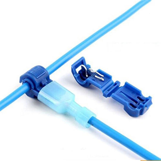
If you're just looking to run more bus wire to the new section, the simplest solution would be some quick connectors:
16-14-gauge-blue-quick-splice-connector.jpg


If this section needs to be removable (not sure if your layout is modular or not), you could try the "T" type variant:
Self-Stripping-Quick-Splice-Electrical-Connector.jpg


These just snap right onto your existing wire with a pair of pliers.
 
We are expanding the layout by adding a 2' X 4' section onto the existing yard section of our L shaped layout. The layout is powered by NCE Power Cab DCC. The bus wires are 14 gauge. The feeder wires are Atlas code 83 track connector type (22gauge). .... The new yard section is basically the track that is sitting on the green insulation in the photos.

The question is what would be the best way to add the bus wire for the new 2' X 4" section. Here is a diagram showing the existing bus wires on the existing 4'X8" and 2' X 8" sections.

Would it be best to wire nut the bus wires into the east end of the existing bus wires on section 2.
Almost yes. I would splice them into the most east end of the bus. Are they twisted? That always makes splicing a bit hard.

DCC Bus 1.jpg


Why do you have a loop back on the 2x8 section to begin with? Could you just straighten it out to go to the new section?
 
Great question Iron. I did not plan on expanding the layout past the 2' X 8' yard (section #2). Well.. actually... I lied to my wife and told her that my son and I would not take any further space in the basement past the addition of section #2. We started drawing up plans for expansion soon after getting section #2 up and running 🤥 We have been honest with her about the fact that we will be expanding further south and east until we have a continuous loop of mainline track that will link the southeast corner of section #1 and the southeast corner of section #3. Which means I will have to decide how to run future bus wires to complete the loop between sections 1 and 3. I am thinking that I will run another set of bus wires from near the NCE panel to the south and east into the future sections instead of continuing the bus from section #3. I hope that all make sense. I welcome any advice and suggestions on this.

The yard (section #2) has 8 tracks across (soon to be 9) the 2' width along with a good number of Atlas 18" snap switch turnouts. In hind sight you are exactly right Iron, I would have run the bus wires differently in section #2 rather than the loop you see in the diagram photo. Another reason for the looping bus wires in section #2 is the fact that I use Atlas code 83 rail joiner feeder wires from the bus to the tracks. My electrical skills are limited and soldering skills are nonexistent. I am envious of Powr and Selector's suggestions in this regard. I probably have way to many feeder wires from the bus wires to the track in section #2. But again... hindsight is 20/20

I will use T-taps as KB mentioned to attach the bus wires for section #3 to the existing bus wires in section #2 just as Iron added to my wiring diagram photo.
 
Well.. actually... I lied to my wife and told her that my son and I would not take any further space in the basement past the addition of section #2. We started drawing up plans for expansion soon after getting section #2 up and running 🤥 We have been honest with her about the fact that we will be expanding further south and east until we have a continuous loop of mainline track that will link the southeast corner of section #1 and the southeast corner of section #3.

Heh... 😁 Shortly after starting my layout, I came up from the basement one day and said. "I just drilled a hole in the wall."
"Why did you do that?" she asked.
"The railroad needed to expand."
"... I was afraid of that..."
🤣🤣🤣🤣
 
I totally understand how you need to take baby steps in the SO approval. I went through the same thing, but planned my whole layout initially and then gradually expanded. My wife now approves after she can see how our family room is still usable for that purpose as well as a usable decent size layout. Life is good.
 
After the munchkins grew up and moved out, my wife sort of took over the two rooms on the second floor, leaving the basement all to me! 😊
A minister, a priest, and a rabbi were discussing the question "When does life begin?"
The priest said "Life begins at conception!"
The minister said "You don't know what you're talking about! Life begins when the baby is born and draws it's first breath!"
The rabbi replied "Oh, neither one of you know what you're talking about! Life begins when the kids leave home!"
 
I wanted to post a follow up and a few photos. I appreciate all the posts on this. I used T-tap connections to run the bus to the new section #3 from section #2 just as KB suggested and Iron drew on the diagram in his post. I also used T-tap connections for the feeder wires as I have in the past. I am happy to report that my son and I got the track in the new section secured, wired, and running this afternoon.

2 X 4 addition 1.JPG
2 X 4 addition 2.JPG


KB, Big, and Fly .......... You provided some much needed smiles after cutting/piecing/recutting track and sitting on the floor under the layout running wires for most of the day. Much appreciated.


Back
Top