super cap balancing question


BBwells

Member
I want to use a couple super capacitors in series and from what I was told was to use Zener diodes as a balancing component. The two super caps are 5 volt 1F and the two zener diodes are rated at 4.7 volts. The supply is 9 volts DC and here is a quick drawing of what I have in mind.
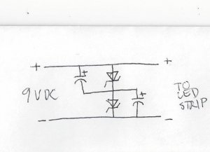
super cap.jpg

Any thoughts as to whether this is correct to insure that the caps only get 4.7 volts and are balanced, thanks.
 
fcwilt, thanks for the reply. I was under the impression that a diode flows current from the anode to cathode but in this application and being zeners, it maybe above my head. I will flip the zeners
and do a little more research on their application. Mosffets are way over my head so this is doable for me. Thanks again.
 
Ok, I think I understand. The current flows through the caps until the voltage reaches 4.7 and the zeners "open" and provide a path of least resistance bypassing the caps?
 
Ok, I think I understand. The current flows through the caps until the voltage reaches 4.7 and the zeners "open" and provide a path of least resistance bypassing the caps?

Well "close" or "short" might be a better way of describing it.

A "normal" diode has a max reverse voltage rating and if that rating is exceeded the diode will break down and start conducting. The diode is likely to be damaged as well.

Zener diodes are designed to take advantage of this behavior but in a controlled and repeatable way.

Frederick
 
Yes, bad choice of words on my part. Both close and short was what I was thinking, provide a path around the cap. It appears that a zener diode maybe also used as a volt regulator. For instance, placed in parallel with a 1.5 volt incandescent bulb fed by say 5 volts provided the zener was rated at 1.5 volts.
These are some interesting components and may have a lot of different usages. Thanks for your time.
 
These are some interesting components and may have a lot of different usages.
Yes you are right. That is why many model railroaders used to buy them by the gross. Demand is getting less and less as more custom model railroad electronics are being developed. I don't think I've had to make a diode matrix for any of my loco headlamps for over a decade now. Yeah for DCC decoders!.
 
Last edited by a moderator:
Diode matrix for headlights? You got my interest. I assume this is to keep the LED headlight on in both directions in a DC loco. Would the matrix look like a bridge rectifier? If so, a standard diode would work but a zener I'm not sure on. Please explain.
 
The zener diodes aren't actually needed.....the way the caps would operate is that the voltage would be divided across them, and they wouldn't see the full 9V.

For example, search for homemade keep alive circuits, and you'll see that the designs just stack multiple super caps in series. The number of caps equals the total voltage feeding the circuit divided by the working voltage of the caps. So, for 16V, using 2.7V super caps, you'd require 6 caps in series. The total capacitance would be the individual values divided by the number of caps.

You'd have to allow for component tolerences, plus a resistor to limit charge current and a diode to allow the caps to discharge when needed are also required, but no voltage balancing is needed.


Back
Top