Scrutinize this N scale layout


videobruce

Tower Operator
First off a little background on myself. I'm a operating kind of guy. As a former brakeman, dispatcher office operator, Tower Operator I like operation. Not really interested in industrial switching. Necessities are;

1. Double track,
2. Long sidings,
3. Plenty of interlockings,
4. A hump yard,
5. A passenger station,
6. A engine house and facilities,
7. Two levels,
8. Around the wall with accessibility without openings in the layout.

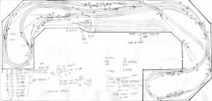
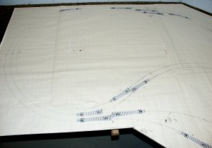
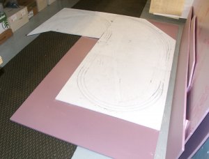
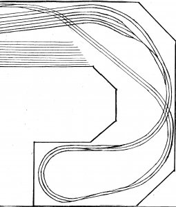
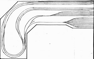
Most of this has been thought of in the attached drawing (left and right side since it is a wide image and the restriction of photo size for attachments.

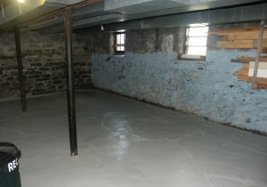
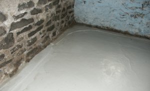
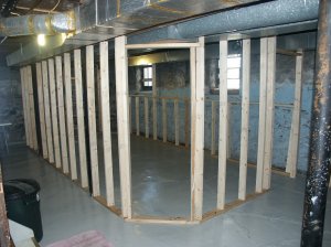
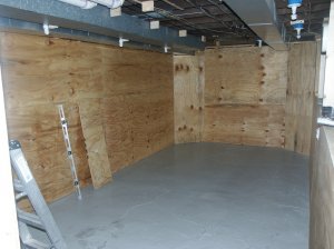
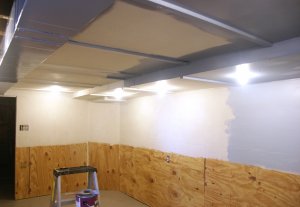
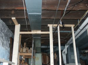
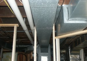
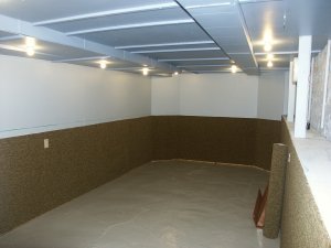
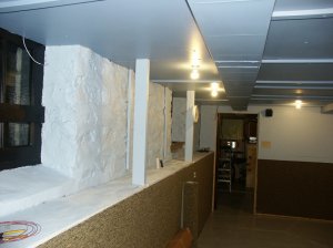
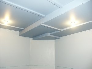
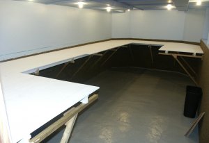
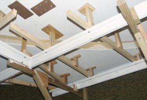
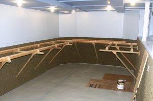
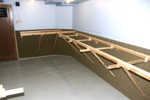
The yet to be built room will be 10x23' in a un-finished basement with a stone foundation. One wall will be the foundation (open, no layout except for a short portion). The built walls (all wood, no cheap drywall) will have the layout in a 'self' like design. The basement get very humid anytime it rains, especially in the spring (varies from as low as 40% to close to 100%). I will have a dehumidifier for that enclosed room. I'm hoping by somewhat isolating the room on three sides and partially enclosing the ceiling I will have a handle on humidity. There is no issue in the winter other than temperature (varies from 40-45 degrees to close to 80 degrees).

Other than the humidity, am I going to have a issue with 'heat kinks' and/or pull aparts?? Those figures are extremes. Temp. ranges from close to upper 40's to upper 70's. High humidity is usually short lived, except under long rainy periods (mostly in the spring).

I talked to a modeler locally in HO scale and he had problems with pull-aparts & heat kinks. But, that was in HO. Is N more or less prone to this?

My first (real) layout was a 5x7' modified 'L' shaped table in a bedroom. For a 1st (real) layout, my major resign fault was excessive grades, especially for the hump. Damn MicroTrains trucks allowed the cars to literally crash into the bumpers at the ends of the tracks sometimes on to the floor. One excessively sharp curve at the top of the grade caused straight-lining with longer trains due to the grades. I have close to 250 freight & passenger cars all with MT trucks & couplers. My power rooster is 23 freight & passenger (Atlas & Life Like), all diesel. No DCC.

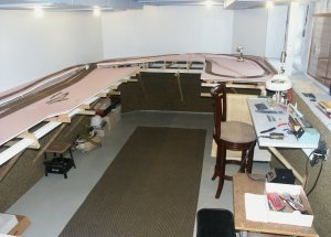
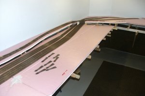
This includes a elevated portion that will include a passenger station with siding off either main. No, there is no 'coach yard' as I don't seem to have room for it without actually seeing it in 3d (after the table frame is built and can visualize the look as it is planned now).
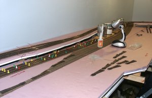
The hump & receiving yard has a engine facilities. I changed the location of the facilities a couple of times and as it stands it needs to be change again since I don't like tracks on either side of the receiving yard 'lead'.

Table depth is limited to three feet since I'm concerned about access along the long wall. I don't want to reduce the depth to 30" since it will 'cram' all of the too close together. It's alot as it is.
 

Attachments

  • layout V2 right full.jpg
    layout V2 right full.jpg
    558.8 KB · Views: 147
  • layout V2 left full.jpg
    layout V2 left full.jpg
    468.4 KB · Views: 163
Last edited by a moderator:
Hi,

I'll let others more skilled than me comment on your plan.... As a "real" operator you probably have a much better handle on it than many here however ;)

Just a couple of comments;

- Over the years I've read about many attempts at doing hump yards - Special cars with magnets, "clever" grading and so on and AFAIK no one's really ever succeeded! (?) It seems the physics are so different that it's impossible to get 'em to go far enough and/or stop 'em appropriately. So, good luck with that! [I'd love to have one too - Would be so cool!]

- I've never done N scale either, but *suspect* it's gonna be even more critical of expansion/contraction than HO! - The tracks gotta be pretty much perfect for those little guys and any rail movement is gonna be magnified. Given regular gaps and hence lots of feeders, I'm sure it could be done but I reckon you may be better off trying to control the environment (?)

Cheers,
Ian
 
Oops - Forgot to ask; Why no DCC?

With all due respect, my 02c, YMMV, etc etc I reckon you've gotta be crazy to try and do a layout of that size with DC!

I admit I'm a huge DCC fan; It was the ability to run multiple engines on the same track that really got me back into the hobby! Then add DCC T/O's, potentially signaling and computer control and I'm a happy camper! :)

I realize "electronics" is "hated" by many, but the ease of wiring alone makes it worthwhile IMHO.

As always, just my 02c,
Cheers,
Ian
 
It seems the physics are so different that it's impossible to get 'em to go far enough and/or stop 'em appropriately.
With the stock Atlas wheelsets, the cars didn't even clear the 'bowl'. With MT, it was the opposite. I came up with a partial solution to use axle grease on one 'point' of one axle of each car as a 'damping' factor, adding or removing some to speed up or slow down the speed. It did help, but there were still fast.
Interesting, I didn't have a lot of problems with the uncoupling magnet. 90%+ of the time the cars 'cut' when they should. The downside was it added 'drag' to all the cars outside of humping operations, but it was doable.

Is a temperature swing between 45 and 78 degrees to excessive?

I have 23 engines (all diesel) that are not DDC friendly that I can't see dealing with. I haven't looked into this yet.
 
...Interesting, I didn't have a lot of problems with the uncoupling magnet. 90%+ of the time the cars 'cut' when they should. The downside was it added 'drag' to all the cars outside of humping operations, but it was doable.

My bad; we're at cross purposes! - I meant using magnets for "damping" in the yard - I saw (at least) one attempt where electro magnets (and obviously magnet equipped cars) were used. IIRC, one was a masterpiece of electronic feedback which "read" the cars speed and de/activated the magnets under the track accordingly - A fabulous idea that still didn't work properly! :(

Is a temperature swing between 45 and 78 degrees to excessive?

I'm no expert, but would guess that's "reasonable". I'm in a nice temperate climate so have no experience - Hopefully someone (preferably in N) will comment soon.....

I have 23 engines (all diesel) that are not DDC friendly that I can't see dealing with. I haven't looked into this yet.

AFAIK, "DCC friendly" simply means you can plug the decoder in to a socket - "Big deal"! I tend to remove the factory board and solder directly anyway..... Having said that, I've only got about 6 locos, so it hasn't been a big issue.

Cheers,
Ian
 
I haven't really looked into DCC, but the little I have read, I now see many/most allow the DCC 'strip' to replace the plastic runner for the headlights and it appears that it just 'snaps' in as you stated.
I will have to open my my power and see, but what I remember none of these have anything like that design. The boards I remember seeing were 50% board, 50% wiring.
 
I was really looking for input on location of interlockings, crossovers & sidings especially at each end of the yard for operational issues.

BTW, I plan two mainline cabs and a separate yard cab.
 
Except for a few feet of track it looks like you have a 3 track main line. You may want to reduce the number or length of passing sidings to define the main line a little more.
Steve
 
I didn't think it was that excessive. I wanted longer sidings, I was concerned about making them too short.
Someone else suggested a 'staging' area. I wanted the ability to store trains off the main outside of the yard.

You can never have too many sidings. Of course, the southern gestapo of CSX thinks differently. :rolleyes:
 
Update on room construction

Attached are photos of the original corner in my basement where the room will go. Including a closeup of the minor seepage/dampness issue, though this is a dryer corner.

Next are views of the room framed.
 

Attachments

  • 01 basement.JPG
    01 basement.JPG
    421.7 KB · Views: 156
  • 02 basement corner.JPG
    02 basement corner.JPG
    422.6 KB · Views: 155
  • 03 basement framed.JPG
    03 basement framed.JPG
    477.7 KB · Views: 151
Last edited by a moderator:
Next is a pic of the obstacle course for the ceiling,
The room with the plywood panels installed.
 

Attachments

  • 05 basement ceiling obstacle course.JPG
    05 basement ceiling obstacle course.JPG
    489.4 KB · Views: 169
  • 06 basement plywood installed.JPG
    06 basement plywood installed.JPG
    425.4 KB · Views: 175
Last edited by a moderator:
I just registered here and saw your post. I hope things are going well with your plans. If you want to seriously tackle your moisture problem you need to stop the moisture from the outside. This would require digging a narrow trench outside the problem wall or walls and installing a drainage pipe to collect and carry water away from the house. Here is a link to a typical installation -
http://www.siliconvalleyzeroenergyh...nt-foundations-perimeter-sub-surface-drainage
If this isn't feasible I would at least dig around the foundation in the problem area, cover the wall with a sealant, available at Home Depot, and fill the trench with gravel to improve drainage and make sure the downspouts from the gutters are intact and drain a good distance from the house.
good luck
 
It appears I do have a handle on the moisture problem. Most of the problems areas seems to be sealed. In the past month we have had a above average amount of rain, sometimes very heavy and no seepage. The basement as a whole is much dryer than past years.

The room is finished except for the top of the 'shelve' along the outer wall. I don't like the 'course' look of the plywood so I think I will use pieces of 'Eucaboard' that were left over from the ceiling to 'smooth' out the surface.

Piecing in the many ceiling sections was a huge engineering problem as nothing was square, each requiring additional trimming. I wanted to use 1/4" plywood, but HD only had two sided finished panels that would of been overkill. before anyone asks, due to the low clearance of the furnace ducts, I couldn't/didn't want to go with a suspended ceiling that would reduce that height another two inches. I wasn't and still not happy with this 'Eucaboard', but it seemed the only solution.

I designed some panels to be removable if need be for access (no plumbing, just some wiring).
 
These were taken a couple of weeks ago. Partially painted with most of the ceiling pieces in place except the outer wall.

The last two were the toughest due to the duct work. Those areas turned out better that I thought since I had no idea exactly how I was to go about covering up the various heights of the different size duct work.
 

Attachments

  • 14 intermediate stage ceiling 01.JPG
    14 intermediate stage ceiling 01.JPG
    561.3 KB · Views: 181
  • 05 basement ceiling obstacle course.JPG
    05 basement ceiling obstacle course.JPG
    489.4 KB · Views: 169
  • 05a basement creative enginnering.JPG
    05a basement creative enginnering.JPG
    422 KB · Views: 146
Last edited by a moderator:
Finished product

I didn't want a suspended ceiling (before anyone asks) due to lack of clearance with the furnace ducts. So I engineered my version of a 'suspended' ceiling using Eucaboard. I wanted to use 1/4" plywood, but the only thing available was double sided finished which would be a waste.
The carpet on the lower half is for sound deadening. Unfortunately, it isn't doing as much as I hoped. Some of the ceiling 'panels' were designed to be accessed for wiring if needed. The unpainted plywood at the floor will be painted gray.

The reason I placed the carpet where it is;
1. I wanted the wall as a backdrop for the layout and carpet wouldn't work,
2. I thought the carpet would deaden the sound under the table.

I probably should of went with a thicker nap, but I thought a flatter, lower nap would look better. Actually from a distance it looks like ground cover. ;)

BTW, six out of the eight CF's in the ceiling are dim-able to around half brightness (three on each of two wall switches). The two on the opposite wall are not which will be over a small 'work shelve' area.
 

Attachments

  • finished room 01 small.JPG
    finished room 01 small.JPG
    461.3 KB · Views: 158
  • finished room 03 small.JPG
    finished room 03 small.JPG
    299.2 KB · Views: 147
Last edited by a moderator:
The ceiling area involving the furnace ducts I thought I would have the most problems with, managed to turn out better than I expected. :)
 

Attachments

  • finished room 07 small.JPG
    finished room 07 small.JPG
    275.2 KB · Views: 137
Last edited by a moderator:
Here is the framework in place, the risers, then the tabletop. No foam is cut yet.
 

Attachments

  • table top in place 02.jpg
    table top in place 02.jpg
    342.6 KB · Views: 151
  • T risers 03 small.JPG
    T risers 03 small.JPG
    208.5 KB · Views: 154
  • framework 01 small.JPG
    framework 01 small.JPG
    663.3 KB · Views: 172
  • framework 03 small.JPG
    framework 03 small.JPG
    678.8 KB · Views: 164
Last edited by a moderator:
updated track plan

I updated my design somewhat. I laid out the plan on paper full size on the table along with Peco templates and fine tuned it to work.

What I don't show is the passenger station and yard as I have run into a problem of space. At the far right, that straight stretch of track on an angle is where it will go. That is elevated. I was originally planning on accessing it from the left (which is from the top of the drawing, but if I do, I have no switching lead forcing me to use the main. If I use the other end, I have my lead (it's drawn in as a siding), but it bars me from using the area away from the freight yard. I loose alot of storage space.

Also, I do not show a engine house, car shop & caboose storage tracks to the left of the hump. The cab track & car shop aren't a big deal, but the engine facility is. I don't know if I should access if from the left or the right off that curved lead from the five track receiving/departure yard.

I also didn't show industrial spurs around the perimeter of the layout as these can be added anytime.

Input please. (there are three attachments)
 

Attachments

  • V4 layout combined.jpg
    V4 layout combined.jpg
    588 KB · Views: 171
  • turnout arrangment 01 small.JPG
    turnout arrangment 01 small.JPG
    440.6 KB · Views: 152
  • foamboard instalation 05 small.JPG
    foamboard instalation 05 small.JPG
    592.5 KB · Views: 134
Last edited by a moderator:
updating thread where I left off

For whatever reason I never updated this thread.
Things went on hold for three years, the following was done during the original stages three years ago. I used CA to secure the track.
 

Attachments

  • track laid far end.JPG
    track laid far end.JPG
    478.6 KB · Views: 160
  • track laid 03.JPG
    track laid 03.JPG
    420.5 KB · Views: 145
  • track glueing 01 small.JPG
    track glueing 01 small.JPG
    763.5 KB · Views: 149
I built a work station/table on the outside wall. below that there is a removable panel to access the foundation wall as there is in the far corner that I can actually get inside and stand up. It's to the far left lower corner in the 2nd attachment.
 

Attachments

  • work station 01 small.jpg
    work station 01 small.jpg
    220.2 KB · Views: 142
  • work station 03 small.JPG
    work station 03 small.JPG
    751.1 KB · Views: 144


Back
Top