Need help with wiring problem


Power routing usually indicates a live frog or frog rails that need to be isolated due to the polarity change that occurs when points are switched from one rail to the other. The frog is live and attached to both diverging rails and thus power routing changes as the turnout is thrown from one rail to the other.

I think power-routing doesn't mean to some folks what it means to you.

Power-routing to me means that power is "removed" in one way or another from the frog-rails of the un-selected route.

If the power is "removed" by making both rails the same polarity then you have the potential for a short.

If the power is "removed" by disconnecting one/both rails then you don't have the potential for a short.

Using this "definition" of power-routing both Electrofrog and Insulfrog ARE power-routing. In Electrofrog turnouts both rails become the same polarity. In Insulfrog turnouts one rail is disconnected.

While the Electrofrog frog is powered (by default) and the Insulfrog frog is un-powered, frog power is a separate issue from frog-rail power.
 
Last edited by a moderator:
I think power-routing doesn't mean to some folks what it means to you.

Power-routing to me means that power is "removed" in one way or another from the un-selected route.

If the power is "removed" as a result of both rails becoming the same polarity then you have the potential for a short.

If the power is "removed" by disconnecting one/both rails then you don't have the potential for a short.

Using this "definition" of power-routing both Electrofrog and Insulfrog ARE power-routing. In Electrofrog turnouts both rails become the same polarity. In Insulfrog turnouts one rail is disconnected.

While the Electrofrog frog is powered (by default) and the Insulfrog frog is un-powered, frog power is a separate issue from frog-rail power.

Yeah, it's not the most accurate terminology. I was just trying to illustrate the difference between fixed power paths and the actual RErouting of power that occurs with the electrofrog. Maybe. I have the concept in my head, but words are harder. I guess more than anything else, I always hear the term "power routing" in reference to frogs and changing the polarity as the turnout is thrown. I still think, though, that the two terms "self-routing" and "self-isolating" are the most accurate ways to describe the two types of turnout, but what makes sense in my own terminology may not be so clear to others.
 
Yeah, it's not the most accurate terminology. I was just trying to illustrate the difference between fixed power paths and the actual RErouting of power that occurs with the electrofrog. Maybe. I have the concept in my head, but words are harder. I guess more than anything else, I always hear the term "power routing" in reference to frogs and changing the polarity as the turnout is thrown. I still think, though, that the two terms "self-routing" and "self-isolating" are the most accurate ways to describe the two types of turnout, but what makes sense in my own terminology may not be so clear to others.

Yes it can be confusing.

But remember that frog-rail power and frog-power are (at least in theory) separate issues.

You could, for example, have a turnout design where the frog-rails have constant power regardless of route selection but have an un-powered frog.

I think Atlas Custom Line turnouts use this approach BUT I haven't used them for years so I don't know for sure.


On the underside of an Isulfrog turnout there are gaps in the ties where you can connect jumpers from the stock rails to the closure rails and then the frog-rails have constant power.

Make that change and the Insulfrog turnout is no longer a power-routing turnout, using my definition of power-routing.


It's not surprising given the multiplicity of turnout designs that folks can get confused.
 
Mike . . . I have now: (1) verified for certain that all my turnouts are insulfrog; and (2) verified that my feeders are properly oriented in relation to main power feeds. Refer to my earlier diagram, where the two loose ends do in fact complete a loop. I still get a short every time I power up with the feeders connected to the ends of the spurs. I tried powering only the yellow side (on your diagram) and I don't get a short, but neither do I get any power to run locos on the siding. And if I throw the principal turnout to the spurs, I get no power on the main loop. Back to square one. Now what?
 
Mike . . . I have now: (1) verified for certain that all my turnouts are insulfrog; and (2) verified that my feeders are properly oriented in relation to main power feeds. Refer to my earlier diagram, where the two loose ends do in fact complete a loop. I still get a short every time I power up with the feeders connected to the ends of the spurs. I tried powering only the yellow side (on your diagram) and I don't get a short, but neither do I get any power to run locos on the siding. And if I throw the principal turnout to the spurs, I get no power on the main loop. Back to square one. Now what?

I'm still waiting for a third party to verify whether HO turnouts work the same as N-scale or not. While Selector seems to think even insulfrogs need to be gapped, Iron Horseman agrees with me that they shouldn't need it. As for the power dying on the mains, do you just have one power drop? If you've only hooked up power in one location, then anything past the turnouts would lose power on one rail once the turnout is thrown. You'd have to have power fed on both sides of the turnout to avoid that. If you put power drops on both sides of the turnout and that then shorts it out in one position or other, then there is indeed power being somehow shared between the frog rails depending on the throw of the turnout.

It's also odd that you can hook power to one rail of a siding and not the other. This shows that you do indeed have the rails sussed out correctly as to which power lead goes to which, or else it would indeed short out in at least one of the two turnout positions. Frankly this sounds like some odd frankenstein of symptoms that don't quite match with a pure electrofrog, which (in at least one turnout position) would just plain short out the layout whether the sidings were powered or not, but also shouldn't be happening if HO scale insulfrogs work the same as N-scale.

Beyond just the wiring advice and checking those two things, I'm probably not going to be much more help. Since I only have N scale turnouts, it's not like I can look at an HO scale insulfrog and try to identify any other problem areas. I guess all I can say now is good luck. Maybe, if nothing else, you could find someone locally to come check it out in person? Honestly I'm just stumped at this point.

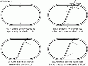
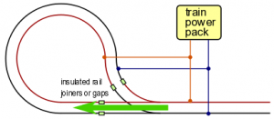
EDIT: Oh, and as far as the main line of your layout forming a "loop", that's fine. The only time you run into an issue isn't with having a circle or oval, it's when the tracks basically double back on themselves and you end up with a positive rail meeting a negative rail when they come back together. These two diagrams may help you suss out the difference. Sidings like you have don't pose any of these issues, because the only through siding you have comes back onto the main with the rails still in the same orientation and not reversed.

image1.gif
RevLoopSingle.png
 
Last edited by a moderator:
Mike ... I have power to the main loop in two places, on either side of the problem turnout ... and it does short out if I throw the switch to permit use of the turnout ... but I did another experiment ... I used a continuity meter to test for continuity between the rails on either side of the frog ... with a turnout just sitting on my desk, there was continuity where it should be, but not where the insulators blocked the path ... so far so good ... but when I put the same turnout into the layout, and hooked it up, I got continuity right through the insulator ... the path obviously couldn't go through the insulator, so it had to be going all the way around, maybe not through the track, but through the power wires ... So ... I went to the PECO website, and looked up instructions for the insulfrog, and although not exactly a model of clarity in expression, they did say gapping was required ... any final thoughts? ...--Gary
 
Mike ... oops, the PECO requirement for insulated joiners (gaps) was only in the situation where overscale wheels might be creating shorts between adjacent frog rails ... my situation does not involve that at all ... so they say no gapping is required ... --Gary
 
Ho! I finally got the PDF to open. We are missing something in all this. Backing up and going back to an earlier post as below:
So I added power to the siding by adding feeder wires, and everything worked fine -- I could run the loco on the loop and the loco on the siding at the same time. The problem is on my full layout. It's basically the same . . . a very large loop with lots of sidings. But when I wired both the main track and the sidings for power, I got a short. Nothing runs. Theoretically, the large layout is the same as the testbed, but the results are different.
So you have actually made a small test layout and wired it up as shown and it worked. It is only the real large layout that has issues. Correct?

When did this first start happening on the large layout? Just when you added the new feeders? How was it run before?
 
Last edited by a moderator:
Right. I made a testbed on a 4x6 plywood board. Simple loop, with one turnout, and a turnout off that turnout. Wired the main loop with power in one location. Ran feeders to the ends of both turnouts. worked perfectly -- I could run a loco around the loop, non-stop, while running switchers on both turnouts at the same time. But when I got the track temporarily laid on my 18'x18' layout, and wired exactly the same way, it didn't work -- shorts. But ... before you reply, let me run to the layout and look at something (and maybe run another quick test). --Gary
 
Nope, no luck. Just tried disconnecting all the other turnouts on the layout, but result is the same. But....to answer your earlier question, the layout works just fine as long as I don't power the turnouts. That is, locos run the main loop (and a couple of concentric loops) just fine. Then, when I put power to the ends of the turnouts, I get a short and nothing runs.
 
Right. I made a testbed on a 4x6 plywood board. Simple loop, with one turnout, and a turnout off that turnout. Wired the main loop with power in one location. Ran feeders to the ends of both turnouts. worked perfectly -- I could run a loco around the loop, non-stop, while running switchers on both turnouts at the same time. But when I got the track temporarily laid on my 18'x18' layout, and wired exactly the same way, it didn't work -- shorts. But ... before you reply, let me run to the layout and look at something (and maybe run another quick test). --Gary

There MUST be some difference between the test layout and the "real" layout.

Questions:

1. Is this a brand new turnout?
2. Did you verify that the bare wires on the underside of the turnout are not touching anything, including each other?
 
View attachment MRR2.pdf
Okay, here's a schematic of the full layout. There are other sidings (turnouts off the main loops), but I've disconnected all of them except the one shown. If I don't add power to the turnouts, I can run several locos simultaneously on the loops with no problem. Only when I add power to the turnouts do I get a short and everything stops.
 
I have confirmed that all turnouts involved are of the insulfrog variety, and the underside wiring is correct. All the turnouts are new.
 
View attachment 53151
Okay, here's a schematic of the full layout. There are other sidings (turnouts off the main loops), but I've disconnected all of them except the one shown. If I don't add power to the turnouts, I can run several locos simultaneously on the loops with no problem. Only when I add power to the turnouts do I get a short and everything stops.

1. If adding power to the frog ends of the turnouts is causing the problem have you verified that you are connecting the wires to the correct rails?

2. You can convert Insulfrog turnouts into "non-power-routing" by soldering jumpers between the stock rail and adjacent closure rail (two places). There are gaps in the ties where this is to be done. Then you wouldn't need separate feeders to the sidings.
 
Mike ... I have power to the main loop in two places, on either side of the problem turnout ... and it does short out if I throw the switch to permit use of the turnout ... but I did another experiment ... I used a continuity meter to test for continuity between the rails on either side of the frog ... with a turnout just sitting on my desk, there was continuity where it should be, but not where the insulators blocked the path ... so far so good ... but when I put the same turnout into the layout, and hooked it up, I got continuity right through the insulator ... the path obviously couldn't go through the insulator, so it had to be going all the way around, maybe not through the track, but through the power wires ... So ... I went to the PECO website, and looked up instructions for the insulfrog, and although not exactly a model of clarity in expression, they did say gapping was required ... any final thoughts? ...--Gary

Right, and I saw your addendum to this about not needing the gaps. Current will be traveling around the wires, as you say, but again if they're not hooked up backward that still isn't an issue. I would think about the jumper wires that are in the turnout across the insulator being mashed together and shorting to each other after installation, but unless you're doing something very weird and specific I don't know how that could have happened on all your turnouts. I have to say that it still just sounds like there are wires hooked up backward, and I honestly can't think of anything else that could be causing what you're describing, especially since you say it only shorts out in one turnout position, and the part of the track that's shorting out changes. If you throw it one way, the siding shorts out, and if you throw it the other way the mains short out. I'm completely baffled at what else could be causing it.

If you're absolutely sure you're getting the wires to the correct rails, I've got nothing else. If you want to triple double extra check that you're not being confused on that, disconnect your siding and use a volt meter. Throw your turnout to the siding and put your test leads with one on the main and the other on the opposite rail of the siding, looking to see that it is measuring voltage on those two points. Then take the meter probe off of the siding (leave it ON the main; don't move that one) and test the voltage again using the wire you think should be hooked up to that point of the siding. If you're doing it right, you'll get the same voltage you just measured on the rails themselves. If you're doing it wrong you'll get nothing, and you'll know that you did indeed have the wires backward.

The thing about it is, if you're hooking up power to the outer rails, which don't ever go through a frog and are one solidly connected piece of metal, and those aren't shorting out, I'm not sure doing the above is actually going to help you any. If it's the outer rails you can't hook up without shorting, then maybe it is just a case of confusion in tracing the rails.

That's really the only remaining suggestion I have.

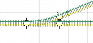
EDIT: Just for a perfectly clear visual aid, this is how your power should be running.

turnout2.jpg
 
Last edited by a moderator:
To Mike: Okay, I'll try that test.
To fcwilt: Yes, one of the first things I did was to verify that the wiring was consistent on the main line and turnouts. But I'm going to run the test Mike suggested.
Now, on your suggestion, I'm using PECO insulfrog turnouts. I don't see any gaps in the ties, but a drop of solder would be easy to make the two connections. Will that suffice?

I added a graphic to my last reply. The gap in the ties is on the bottom of the turnout, so if you already have them installed you won't be able to get to it without taking them back up.
 
BTW, I live in the country, between Driftwood and Wimberley, TX. Just on the off-chance one of you knowledgeable folks lives in the area :).
 
BTW, I live in the country, between Driftwood and Wimberley, TX. Just on the off-chance one of you knowledgeable folks lives in the area :).

If it were more Dallas than Austin, I might consider it. 7 hours on the road would be a bit much, though :)


Back
Top