Momentary occupancy detection


tankist

Active Member
I looked at options to buy such device for the purpose of protecting and disabling occupied turnouts. it seems that options are limited to rob pailey's circuit (any one here bought his product?), or the overpriced one from micromark.

any other options available? thanks!
 
well, since i'm looking at 16 sensors the expense seems to be more then trivial. over the weekend i bread-boarded a working prototype circuit, expanding on RP's voltage comparator concept. this evening i worked on a PCB for a 4 channel device. local indication LEDs are mounted on board. to prevent any issues with current leakages and/or grounding the circuit has opto-isolated outputs (that will connect directly into digitrax or team digital device inputs). to save space on PCB all the connectors aside of power are headers and high density ICs are used. as modeled so far it fits on 3x1 inch footprint (quick 3D model attached).

wondering if there might be interest on part of others in either the PCB or the ready circuit. i don't intend to make it a business but while i'm etching my 4 PCBs (or two doubled up ones) i might as well do couple more.
 
Here is the solution that I use which in effect solves the problem.

1) I have installed on all of my rolling stock and engines at least one set of resistive wheel sets (generally one set at each end of the rolling stock). This will cause a very low current drain from the rails (about 10 ma which is enough to trip most block occupancy detectors but is so small as to require 100 wheel sets (50 pieces of rolling stock) to draw just 1 amp. Most of your upper featured DCC command systems can supply 5 amps. It is relatively easy and the cost is not that great to add a booster should your layout demand more power than the basic command system can provide.

2) I isolated the turnout in such a way as to cover a section of track at least one full rolling stock car length in every direction away from the turnout. This will allow for monitoring a train passing through a turnout but where there might be a momentary time when there is nothing on the rails of the turnout itself. I do have a couple of passenger cars that are longer than my turnouts.

3) I installed a block occupancy detector that can sense current draw from within this isolated block. I prefer to monitor the actual current flow via the monitoring of a diode circuit rather than detect the current flow via some sort of detection coil.

4) The block occupancy detector disconnects power to the device that control the turnout points any time the block occupancy detector detects that the block is occupied.

I have not had a failure where a turnout was thrown while a train was traveling through the turnout in my current layout which has been up an running since the spring of 2007 nor the previous layout for which I started using DCC in the Fall of 1994 through the end of the summer of 2006.

This works well for me. But there are two issues that must also be considered.

1) My block occupancy detectors must be able to detect a current flow in order to cut the power to the turnout control device. This means that power must always be available to the block when there is a piece of rolling stock or and engine within the block. This circuit will not work for DC if the train is stopped because there will not be a current flow.

2) My block occupancy detectors detect the flow of current by measuring the current flow through a bridge rectifier. This means that there is a slight voltage drop (1.4 volts) through the bridge rectifier which means that the top voltage in the detection block is lower than the top voltage in a non detection area of the layout. My cure for this issue was to install a full bridge rectifier between the power to the rails and the rails for each electrical block.

Now for what it is worth I use DCC to power my layout. I use all Digitrax components to control my layout to include their power management devices, block occupancy devices, turnout control devices, and signaling devices. All of my mainline and many of my spurs, sidings, and yard areas are also protected. Not all areas are monitored for block occupancy detection but all areas do have the same current monitoring sensors and thus the voltage drop to the rails is the same.

Now as a side benefit I have a full working signal system on my mainline which gives the layout a feature many layouts do not have. I also have a local panel that monitors the occupancy of each siding of my hidden yard. As a final benefit to this type of installation I have a computer software program that indicates which blocks are occupied, what the routing status is of each turnout, when a short circuit occurs which areas of the layout are effected, what the signal status is for each signal aspect, and which engine is where along with where specific rolling stock of interest is located.

As for where I get my wire I use local places that have the best prices. I use 20 awg for my feeders which I get at Radio Shack and my main bus wire from Lowe's. I got a 14 awg a 500' spool of red and a 14 awg 500' spool of black for $35.00 each at Lowe's.

Al
 
thanks for your reply.
i don't want to modify cars or at least do as little as possible. i do not see installing resistive wheel sets on every car as viable solution. besides, thats also means every turnout will have to be isolated, have its own set of power leads and use a block detection channel. you also will not be able to protect against running open turnouts since you do not know which route train approaches, that's why i went for optical solution for turnouts (i have regular block occupancy detection in place already).

I prefer to monitor the actual current flow via the monitoring of a diode circuit rather than detect the current flow via some sort of detection coil.
i preffer coils since there is no voltage drop and circuits completley isolated. but its your choice obviously.


circuit in progress got some additions: timer for delayed release and a rectifier to work with any power, DC or DCC. so far i spent close to 60$ on parts and supplies including etching solution and blank board. enough to produce about 10 of these boards, lol. the chineese sellers tend to sell in packs of 50-100 parts and i like having extras.
 
I looked at options to buy such device for the purpose of protecting and disabling occupied turnouts. it seems that options are limited to rob pailey's circuit (any one here bought his product?), or the overpriced one from micromark.

any other options available? thanks!

I would NOT use a detector like that because it has no sensitivity control. It relies on detector voltage going to half of supply rail to do a sensor detect.

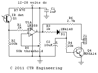
The circuit I showed you (that I use) has a pot that sets threshold. This makes it significantly more sensitive and reliable.

The ultimate would be to modulate the IR transmitter and use a bandpass filter to detect that frequency, with some internal level adjustment to keep the system in a linear part of the detector curve in the presence of strong external light.

I have not found modulated IR sources necessary at all. I can easily go four feet distance in a room exposed to morning sun. I can set a detector outside and carry it in the barn and still get good sensitivity using high power IR LED's.

I can't imagine using load current detection. I thought about it, but ruled it out. If I wanted to detect, I also would not use a bridge. I would either use a Hall-effect cell or I would use a pair of back-to-back diodes and detect the voltage drop across them. At least then, with suitable diodes, voltage drop could be kept down to less than 1/2 volt.

If I wanted to detect a train or train car on a stretch of track using something other than IR detection, I can think of at least two or three ways to do this using the rails electronically without impacting any system in any way. Unfortunately I got screwed out of some patents by talking about ideas too much, and I think some of my detection ideas could probably be patented and maybe for profitable applications. :)
 
Last edited by a moderator:
i went with that instead of yours partially because i have boat load of comparators already. as far as threshold being adjustable all it takes is installing a trim pot. which i am not planning to install - i found the suggested value working perfectly in my lighting conditions, and those conditions are not going to change much. i do not plan on running a "night mode" but in that case i will just disable the protective logix for that session.


for modulated IR i found a nice writeup of ATtiny13 controller based circuit (with code). the code knows to separate the modulated IR signal from the 50Hz interference of daylight and incandescent lighting. i do have a programmer, but i do not have that part at hand. and frankly i'm a bit scared of controllers :rolleyes:

what i'm really excited about is to actually try toner transfer for PCB fabrication.
 
i went with that instead of yours partially because i have boat load of comparators already.

Op amps are pretty much op amps for an application like this. It is non-critical low impedance stuff.

as far as threshold being adjustable all it takes is installing a trim pot. which i am not planning to install - i found the suggested value working perfectly in my lighting conditions, and those conditions are not going to change much. i do not plan on running a "night mode" but in that case i will just disable the protective logix for that session.

OK. I wanted distance and reliable day/night.

You should, with enough IR transmit level and a narrow beamwidth IR detector, not have any issues. I don't.

for modulated IR i found a nice writeup of ATtiny13 controller based circuit (with code). the code knows to separate the modulated IR signal from the 50Hz interference of daylight and incandescent lighting. i do have a programmer, but i do not have that part at hand. and frankly i'm a bit scared of controllers :rolleyes:

You must be in some foreign land. :)

The modulation is normally 2x the power line frequency. 100 Hz for Europe and 120 Hz for NA. This is because lights blink twice each cycle. Each blink is a pulse, or one cycle to the decoder.

Since the light source (and detector) is likely non-linear, I'd expect considerable harmonics. Especially odd harmonics like 3,5 and so on times the basic frequency of 100 Hz or 120 Hz.

I'd avoid an encoder/decoder a low multiple of power line frequency. Personally, I'd just build an op-amp bandpass filter either below base frequency or far above it....maybe up around 1 kHz or so.

what i'm really excited about is to actually try toner transfer for PCB fabrication.

I used to print transparencies and use photo resist boards. I think it was Xylene or something healthy to drink we used to remove the unexposed photo-resist areas. Then a bath in hot agitated ferric chloride.

Now I just pay to send a Gerber file to a board house for proto's. :)


Tom
 
well 50-60, same thing, you got what i'm talking about :rolleyes: that writeup indeed happened to originate outside of US.

i was shopping for photoresist on ebay and last second before i clicked "buy" i stumbled on something that was sold as "toner transfer paper" , looked into it, found a bunch of youtubes and it seems as good minus the laminating, exposing and developing part. already secured the old iron for that . now fighting with PCB design software.

while perhaps justified pricing of some places i looked at is above what i'm willing to pay, so i try to get by

I'm pretty sure I have boards and chemicals here still for photo etching, if you want them. I'll have to make sure they are good.

We quit etching here and just bite the bullet and pay for outside professional etching. It is about 33 dollars per board plus shipping, but they allow 60 square inches per board. If you are clever and array boards correctly, a bunch of useful boards can be in one sixty square inch $33 board. They have a 4 board minimum and give one free, so that is 300 square inches for about 150 bucks or .50 per square inch.
This gets a double sided silk screened solder mask board with plate throughs as required.

My photo-detectors are four dual channel detectors on a board, with four dual control relays on each board. That gave me 40 detector blocks and 40 control relays in one $150 order. That's $2 per function block for board cost. I have not used the actual relay boards yet because I wired up a dead-bug prototype board first. I wanted to debug my wiring and get stuff running.

What I plan on doing is building the professionally etched boards and installing them as a nicely wired system after everything is proofed. It looks like I'll need about 30 relays, and only use about 15-20 location detectors so I'll have spares for expansion.


To tell you the truth I would just buy some raw single-side and use a dremel to cut external connection pads, and build the thing dead bug style rather than self-etch. Did you think about using proto boards like the perf board with copper traces on it??? it's drilled for IC chips and has basic traces. You'd just have to do minimal signal wiring and no drilling, etching, or cutting.
 
...
To tell you the truth I would just buy some raw single-side and use a dremel to cut external connection pads, and build the thing dead bug style rather than self-etch. Did you think about using proto boards like the perf board with copper traces on it??? it's drilled for IC chips and has basic traces. You'd just have to do minimal signal wiring and no drilling, etching, or cutting.

oh no, thank you. i worked with perfboards enough to know i do not want to t touch them at this level of complexity. time spent on developing the board and etching will be compensated ten fold by the ease of mounting and and less mistakes.
 
oh no, thank you. i worked with perfboards enough to know i do not want to t touch them at this level of complexity. time spent on developing the board and etching will be compensated ten fold by the ease of mounting and and less mistakes.


How many boards do you need?
 
i'm working with 4 channel groups (due to use of quad comparator and OC chips ), 2 groups per board, 2 boards total. way to many to trace by hand and to little to order
 
version of the PCB is ready.
board handles 8 photo-transistor detectors. there is about a second signal release delay after detector goes inactive (accomplished with 555 timer ICs). output is via 8 LEDs and optically isolated 10pin header connector. coincidentally layout of the 8 output pins matches perfectly the layout of 8 inputs on Team digital SIC24AD devices that i have on order. the size is 4x4 which will match the long side of the signal decoder. traces are 1mm wide so it should be doabe even with less precise techniques.

the use of space and layout of parts might be not efficient, but so far only few connections have to be added as jumper wires.


so i finalize the board layout and then stumble on simplified circuit using 2 less ICs :mad:
will breadboard the concept and then back to drawing board... :eek: :rolleyes:
 
Are you sure you cannot easily eliminate the 555 timers??

A simple RC integrator on the op amp outputs probably can act as a time delay.

555's or 556's are great if you need the straight line part of the timing charge-discharge slope, but I don't think that is required to integrate the output of a system like this.
 
well this board i will not be making. chalked time spent as my first learning experience. i'm already planning circuit without the timers. something like this but without the transistir.

PhotoBasicRelay.GIF


could you draw an RC integrator and how it connects to opAmp/comparator? will this be one comparator per channel. again, using comparators here since i have a supply of them.
before venturing into timers i breadboarded the comparator circuit and could not achieve a output release delay. (i did achieve exactly the opposite though - activation delay, lol)
 
well this board i will not be making. chalked time spent as my first learning experience. i'm already planning circuit without the timers. something like this but without the transistir.

PhotoBasicRelay.GIF
What IC is IC1? If it is not an open collector output, it will not work properly.


could you draw an RC integrator and how it connects to opAmp/comparator? will this be one comparator per channel. again, using comparators here since i have a supply of them.

What comparator or op-amp do you have?

What you want is fast-attack slow-release on the output. That generally requires a method of creating a different charge and discharge rate in a capacitor, so it charges from one source impedance and discharges through a much different impedance.

The leading edge, upon trigger, needs to have a low impedance source or load (depending if the logic is going high or going low upon trigger). Then you want a much larger release impedance (going high or low) so the capacitor has a longer time constant on release.

The most economical way to do this is to plan the design so one component serves multiple purposes. For example modifying the circuit I posted earlier we could have something like this:

Model%201.gif


In this case C2 charges faster through R3. It discharges slower through R4. A very slight on-delay depending on the value of R3 and C2, and a MUCH longer off-delay that could be set by the value of R4 and C2.


Time constant is R*C or .01 seconds for attack and .1 seconds for release. The attack and release voltage threshold is 1.4 volts or so, and the peak charge voltage is around 12 volts or so.

This means the transistor comes on as it crosses 1.4 volts on the way up to 12 (fast) but turns off after the 12 volts discharges to way down from 12 to 1.4. LONG time.

At .1 seconds C4 would be 37% of 12 or 4.4 volts.

At .2 seconds it would be 37% of 4.4 or 1.6 volts.

Scaling C2 or R4 up would increase the time.

This is just a rough example to show how a fast attack slow decay would work, and not to be taken as a working system. The beta of Q4 and sink current on the collector would limit the upper size of R4, and I'm not going to spend time to do a total analysis of the system. :)

Tricks like this are used to reduce cost and complexity, because components can serve more than one dedicated function. There are probably a half-dozen ways to make the system fast attack and slow decay without adding more IC's.

It's almost certainly possible to loop around the comparator with an RC circuit to make a long delay on release without the darlington stuff and use smaller value caps, but I have to get back to work now.

Tom
 
thank you for your time.
i will be playing with this this evening - since i'm less knowledgeable as far as the actual math behind this topic i breadboard everything i build before soldering. i had a hunch it is could have been accomplished much easier, but i'm using the blocks i know about. now i know bit more :)

less components and less drilling is sertainly welcome


EDIT, oh the IC is LM393 or in my case it's quad version - 399 ()
 
Last edited by a moderator:
thank you for your time.
i will be playing with this this evening - since i'm less knowledgeable as far as the actual math behind this topic i breadboard everything i build before soldering. i had a hunch it is could have been accomplished much easier, but i'm using the blocks i know about. now i know bit more :)

less components and less drilling is sertainly welcome


EDIT, oh the IC is LM393 or in my case it's quad version - 399 ()

A 399 is a heated voltage reference.

http://cds.linear.com/docs/Datasheet/LM199399fb.pdf

A 393 is an op amp

http://www.national.com/ds/LM/LM193.pdf

The 393 is NOT open collector, so the circuit posted:

PhotoBasicRelay.GIF

Any standard op-amp won't be fast-attack slow-decay. IC1A will try to discharge and charge the 3.3 uF fast unless you add a blocking diode or use an open collector output!!!

If IC1A is open collector output it will a fast low and slow high, because the 3.3 will charge through the 1 meg and discharge through the output impedance of IC1A as it sinks current.

No cigar on the hang time in the bottom circuit above.

Tom


Back
Top