Kato F7 A issue???


goscrewyourselves

I'm the one
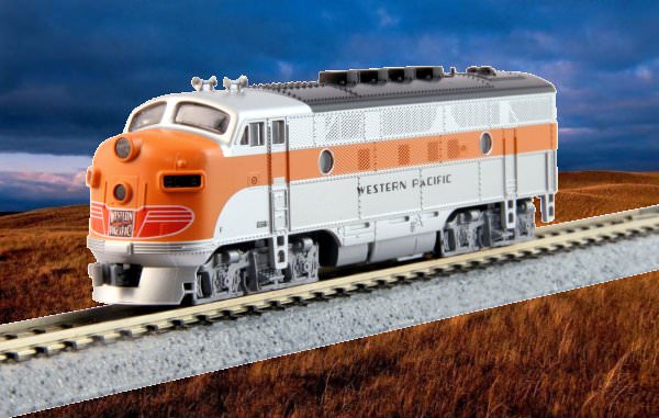
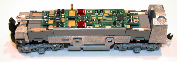
A week or so ago I inadvertently burnt out the TCS decoder on my F7 A. The decoder was replaced by TCS and this evening I was going to install it. Before doing so though, I checked the engine itself for operation by connecting wires from my NCE to the Motor Tabs on the engine. The only thing that happened, or I heard, was a "buzzing sound" from the motor.

I assumed that was a good thing so installed the decoder (brand new). Placed the engine on the track and nothing, naddah, no motor sound (buzzing) no movement, dead as a door nail.

I am assuming the decoder is okay as it is new; as such I am thinking there is something wrong with the engine itself. Could that be the problem and, if so, what might the problem be and is it repairable?

I don't know if it is me or this engine just doesn't like me as I have never had problems with any others.
 
Tony: Have you tried running the engine's motor on straight DC current to see if it operates without a problem. Another problem could be one of the truck's drive gear jammed and not allowing the motor to spin.

Greg
 
I was going to suggest testing on DC, as the theory goes, if a new decoder will run on DC, it will also run on DCC. What address did you use to test it with? All new decoders have short address 3 as the default to begin with.
 
Ah, I just re-read your first line about connecting the cab to the motor tabs. Without a decoder fitted, that won't work.
 
Tony: Have you tried running the engine's motor on straight DC current to see if it operates without a problem. Another problem could be one of the truck's drive gear jammed and not allowing the motor to spin.

Greg

Greg,

Not yet, have to dig out one of my old DC controllers but will and see what happens.

Toot'n,

Yep engine 03, controller 03 :) And to clarify, when I said I was attaching power (albeit the wrong type) directly to the motor tabs of the engine, that was just to test the motor of the engine to see if anything was wrong with it. From what I understand, doing that "should cause" the motor to spin and wheels to turn. If that happens, I could rule out the problem being caused by the engine.
 
One last question (I think) ...

Will a Kato F3 body/shell fit on a Kato F7 frame? In other words, are F3 and F7 bodies inter changeable?

Reason I ask is because I have found a Kato F3 with DCC installed for less than a $100. IF the two engine shells can be swapped with each other, I'll just buy the F3 and swap the shells over.
 
Okay found out the F7 and F3 shells are inter changeable so have bought this Kato F3 with TCS DCC installed. I'll swap out the shells though:

GZhs6tb.jpg
 
And to clarify, when I said I was attaching power (albeit the wrong type) directly to the motor tabs of the engine, that was just to test the motor of the engine to see if anything was wrong with it. From what I understand, doing that "should cause" the motor to spin and wheels to turn. If that happens, I could rule out the problem being caused by the engine.​

Cheers,

What you are describing there (using DCC current direct to the engine tabs) is the same as putting a DC only loco onto DCC rails, which won't make it turn or run, but will make it hum, which is what it appears to have done. Eventually the motor would fail if applied for too long. DC current is the smoothest flowing form of electricity, the reason it is chosen for model motors, and what the motors in our DCC locos actually use anyway, via a rectifier in the decoder.

DCC is a wave form current, similar to AC, in that it alternates between a high and low side, but different to AC in that the wave form is angular, where AC has a smooth sea-like wave, with peaks and troughs. Just what all that means in how it is actually able to do what it does, someone with a greater understanding will have to advise (or correct). The basic thing we as modellers, using either DC or DCC need to remember as it applies to model trains, is that with DC track, we control our trains by varying the current between 0-12V or more, whereas DCC track is at a constant voltage of 14+V, and the decoder varies the rectified DC current to the motor, according to the commands from the Cab. I find that is the part that most ex-DC users have the most trouble getting their heads around.
 
Toot'n,

Thank you for the detailed explanation and differences between DC an DCC. I have read other explanations but none quite as straight forward as yours.

You are correct that the sound I hear is the sound a DCC engine makes on a DC track. Fortunately, I only left the "power" to the motor on long enough to hear the Hum or buzz, only a second or two at most so I doubt I have hurt anything, touch wood.

When I applied the DCC current (hope that is the right way to put it) to the motor tabs I got the hum sound. That tells me that power, albeit the wrong type of power, is getting to the motor and that the motor is okay. That is to be confirmed using DC power though.

So, IF there is nothing wrong with the engines motor, which spins smoothly and freely by hand, then why does it not move when a brand new DCC decoder is installed (as per the instructions - to the letter as I have done a few times before)? Rhetorical question at this point.

If the motor gets it power via the decoder, and the motor does nothing (literally) with a new, properly installed decoder in it then reasonably the problem is the decoder. Would that seem logical?

Now, when I tested the decoder, after the engine did nothing, by placing leads directly to the tabs of the decoder the motor tabs are attached to, nothing happens other than the two (2) decoder components (shown in red in the following diagram) burst into flames. The ONLY thing I touch with the leads is the center of the tabs on the decoder. In other words, I am not touching anything with the leads that may inadvertently cause a short.

l0hifzG.jpg


This particular engine has given me issues from day one, in one way or another which is why I bought the F3 shown above. I don't know Toot'n, seems everything works properly individually (decoder/motor) but when combined ... nothin'!
 
If the wires you were touching to those tabs were coming direct from your cab, then you were bypassing the decoder, and applying DCC current directly to the motor and presumably into the decoder in the reverse to what it should. They should have touched to the track pickup tabs that the wires coming up from the trucks connect to. If doing that had got the motor to turn, then it should have run off the track power anyway, unless there are breaks in the wiring from the trucks (have had wires not connected to those myself from new).
 
Toot'n,

Loos like I have been given some incorrect advise then OR, advise that I misunderstood. So, just so I am 100% clear on what I need to do ...

I need to use either a 9 volt battery OR DC controller.
Attach wires to either of the above
Attach, touch the other ends of the wires to the "truck power tabs" and see if the wheels then turn.

If the wheels turn on both trucks, after testing both trucks, then all is well with the engine or at least the motor. If that is the case, then there is an issue with the decoder/s OR something between the decoder and the truck pick ups where the power is not being distributed to the truck power tabs.

Am I now on the right track mate?
 
Any input power, if the decoder is fitted, must be applied to those track pickup tabs/connections on the decoder. As most, if not all, decoders these days are dual DC/DCC capable from the maker, then applying DC power from any source, batteries or DC power pack/controller, to those tabs, should cause it to move. The decoder has the ability to determine which type of power is entering it and adjusts accordingly. Only proviso is a 9V battery will probably make it leap away from you. If it was a sound decoder, I wouldn't use a battery, too sudden a voltage inrush. Actually, I would avoid using a battery in any case for that reason.

If you want to just test the motor, remove the decoder and use the tabs on the motor. (afterthought) Do your testing with it laying on it's side, can't run away from you and you'll be able to see if the wheels move. If it works OK and all the wheels turn, then time to test it on the track. I have my test track set up with both DC and DCC connections, so I can do that initial DC test. If it responds on there to DC, then I know that all the connections from the track are OK. If it doesn't respond to DCC, then the decoder is faulty.
 
Toot'n,

Thanks again mate. What I have decided, at this point, is to replace the engine with new one (DCC installed) and then worry about getting the "problem child" sorted out. If I do find the problem and it can be fixed then I have another F7. If I don't, at least I'll have one that works.
 
An Athearn I bought had a dud motor, if the armature stopped in a certain position, it wouldn't start again. Anywhere else it was fine. Figured there was a break in the wiring wound around one of the armature poles.
 
Okay, so finally got myself a 9 volt battery and the good news is - the motor runs and everything seems fine. Therefore, it has to have something to do with the decoder OR the motor tabs from the decoder, right?
 
By the sound of it, these tabs rely on just contact to create the connection? If so, maybe try a bit of finger pressure to see if they're not doing so if that's possible.
 
In DC mode, you are right - I think. As soon as I touched the motor tabs with the wires from the battery the motor turned and the wheels turned along with it. Everything seemed to be working as it should - in DC mode. That suggests to me that everything required between the motor tabs (where the power comes in) and the wheels is okay and there are no issues. Theoretically, if I were to reinstall the factory fitted light board, the engine would run. Can't re install it as I no longer have the clip to hold it in place by the way.

So (in DC mode) power comes up from the track, through the wheels to the two brass rails via tabs (from the trucks) that are connected to the motor tabs and everything works. Choo choo go back, choo choo go forward! :)

Enter the dragon, aka DCC Decoder. The two rails and chassis are now insulated from the motor tabs that are soldered to the decoder pads, preventing the track power from getting to the motor and causing a short. Now the power comes from the controller through the decoder to the motor tabs down to the motor that makes the wheels turn, more or less. How does that sound for a very novice explanation?

Assuming my understanding is right AND everything worked in DC mode, the only thing left that could be the problem is the decoder - correct? Reasoning, works great in dc mode, install decoder and nothing.

If any of my logic is wrong, what am I missing?

Now a curiosity question separate from the issue question:

Now if (again) what I am saying is right then, once a DCC Decoder is installed, what is the purpose of the two brass rails that connect with the tabs from the trucks? They essentially become redundant don't they as they now serve no purpose?
 
I went back to the picture in post 9 with the DCC decoder sitting in place. Now I can see that there are 4 longish tabs above the trucks, and on the decoder, short tabs at each corner, but not connected in any way to those ones above the wheels. These brass rails you mention for DC operation. As you describe them, they would be for DC operation only. In the picture, the corner tabs on the DCC decoder are in the usual place that the track pickups from the trucks would normally be, but there doesn't seem to be any possibility of a connection to the trucks. There's a gap.

If this is truly a drop in decoder, then I would expect those corner tabs to be long enough and bent down at the ends, so they make contact with the truck tabs. There's no other parts included with the decoder to push onto those corner tabs to achieve that is there?
 
Toot'n,

Nope, the decoder is just that one piece and flat as a tack on the bottom. The decoder is a replacement for the one I fried and the only difference between the F7A decoder and the F7B decoder is the addition of the LED for the head light etc on the F7A one. Other than that, they appear to be identicle. Why I mention that is because the B unit runs fine with the decoder in it.

Okay, just had a brain spark! Because of the problem I had with this F7A engine not running with the decoder installed and the shell in place, I removed and reinstalled the decoder maybe 3 or 4 times trying to fix that problem. Is it possible that soldering and unsoldering the motor tabs so many times has cooked something? Just too much heat being applied too many times? Or, too much solder build up on the motor tabs?

I have a new F7B decoder for another B unit. If I am right about the A and B decoders being the same, other than the light, I could see if that worked in the A unit. However, if there is a problem that might be causing the decoders to short, I don't to fry another one. Or, if there is something like I suggested above, then putting in a new decoder wont solve anything.
 
Last edited by a moderator:


Back
Top