Didn't realise you had to solder the motor to the tabs, but so long as you didn't hold the iron on too long, the decoder should be OK. But that still doesn't answer where the power from the tracks/trucks connects to the decoder. How does the B unit's decoder connect to the trucks?

You are using an out of date browser. It may not display this or other websites correctly.
You should upgrade or use an alternative browser.
You should upgrade or use an alternative browser.
Kato F7 A issue???
- Thread starter goscrewyourselves
- Start date
goscrewyourselves
I'm the one
No idea mate, I just follow the directions for the installation and it works. Give me a sec and I'll remove the shell (uh ohhh) from the B unit and have a look to see what, if anything, I can see.
Actually, I have a better idea! I ordered another F7 with TCS installed, that is arriving sometime this morning. When I remove the shell from it so I can put my painted shell on I'll snap some pics so you/we can see how it should look and maybe even what goes where.
Maybe I can use the two as a comparison to see if there are any major differences.
As mentioned (I think) I will have a new engine so getting this one working isn't a big issue I just can't stand not knowing what the issue is")
Actually, I have a better idea! I ordered another F7 with TCS installed, that is arriving sometime this morning. When I remove the shell from it so I can put my painted shell on I'll snap some pics so you/we can see how it should look and maybe even what goes where.
Maybe I can use the two as a comparison to see if there are any major differences.
As mentioned (I think) I will have a new engine so getting this one working isn't a big issue I just can't stand not knowing what the issue is
Last edited by a moderator:
I just can't stand not knowing what the issue is
Same here
, see ya later (or maybe earlier in my case, if I get the chance)goscrewyourselves
I'm the one
No problem mate, catch you in the morning and thanks for persevering with this with me.
goscrewyourselves
I'm the one
So, here is my new Kato F7 A with TCS DCC factory installed engine:
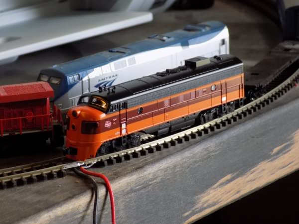
Out of the box and onto the test track and, as I expected, it ran beautifully. This is the engine that will carry the "Royal Pacific Railroad" paint scheme. What I will do with the Milwaukee Road shell is anyone's guess.
Out of the box and onto the test track and, as I expected, it ran beautifully. This is the engine that will carry the "Royal Pacific Railroad" paint scheme. What I will do with the Milwaukee Road shell is anyone's guess.
goscrewyourselves
I'm the one
Okay, will it never end!!!!! Apparently all F7's are not the same. It seems as though this one (the one above) is longer than the one I already have. Therefore, the shells aren't inter changeable ... hell, why would they be?????
Okay, so I have just ordered yet one more TCS Kato Drop In F7 A (specific) decoder for my "problem child". If that doesn't work then I'm giving up, moving to an isolated never been heard of before island and contemplating the meaning of life
Okay, so I have just ordered yet one more TCS Kato Drop In F7 A (specific) decoder for my "problem child". If that doesn't work then I'm giving up, moving to an isolated never been heard of before island and contemplating the meaning of life
goscrewyourselves
I'm the one
Greg,
It is a beautiful engine, no argument there. I know you are a Milwaukee Road person so don't take this wrong, it just isn't a paint scheme that I am personally fond of.
Not that I know of. I live in the bush so the closest hobby shop to me would be about 2 hours away, and from what I understand, all the people there do is sell and nothing else. There is a "club", if you can call it that, about 15 minutes up the road from me but that is purely HO and the handful of people in it are, well - all too full of their own self importance to bother with anyone who isn't apart of "their little click". I was a member there for a couple of months and it was all anyone could do to talk to me ... I don't drive a late model Mercedes or BMW if you know what I mean
It is a beautiful engine, no argument there. I know you are a Milwaukee Road person so don't take this wrong, it just isn't a paint scheme that I am personally fond of.
If the problem with the other locomotive continues, is there a local installer of DCC that could look into the problem for you?
Not that I know of. I live in the bush so the closest hobby shop to me would be about 2 hours away, and from what I understand, all the people there do is sell and nothing else. There is a "club", if you can call it that, about 15 minutes up the road from me but that is purely HO and the handful of people in it are, well - all too full of their own self importance to bother with anyone who isn't apart of "their little click". I was a member there for a couple of months and it was all anyone could do to talk to me ... I don't drive a late model Mercedes or BMW if you know what I mean
goscrewyourselves
I'm the one
Okay, I was taking a very close look at my problem child and saw this:
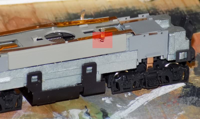
It seems the same on the opposite side as well but not as bad. I am guessing this isn't good and "may be" part of the reason it wont run with a decoder in it?
My guess is I touched the side with my soldering iron or had it too hot when attaching the motor tabs to the decoder.
It seems the same on the opposite side as well but not as bad. I am guessing this isn't good and "may be" part of the reason it wont run with a decoder in it?
My guess is I touched the side with my soldering iron or had it too hot when attaching the motor tabs to the decoder.
goscrewyourselves
I'm the one
Greg,
Good question, I have a Hakko FX888 soldering station with adjustable temp settings from (I think) 250 F to 750 F. According to their site the Soldering Station is rated at 70 watt and the Iron at 65 watt. I left everything as was (default) with the temp set at 750 F. Might need to turn that down just a tad?
Good question, I have a Hakko FX888 soldering station with adjustable temp settings from (I think) 250 F to 750 F. According to their site the Soldering Station is rated at 70 watt and the Iron at 65 watt. I left everything as was (default) with the temp set at 750 F. Might need to turn that down just a tad?
Burlington Bob
Well-Known Member
Tony, the reason your Milwaukee F7 shell is longer is because it's a FP7. The difference is that EMD added four feet to make room for more water storage for the steam generator for heating passenger trains.
goscrewyourselves
I'm the one
Bob,
Thanks and yeah, once I looked at the Jewel Case I saw it was an FP 7, something I didn't pay any attention to when I ordered it, all I saw was F7. As said, if nothing else I have a very nice additional engine.
As for the reason for it being longer - let the passengers wear coats!
Thanks and yeah, once I looked at the Jewel Case I saw it was an FP 7, something I didn't pay any attention to when I ordered it, all I saw was F7. As said, if nothing else I have a very nice additional engine.
As for the reason for it being longer - let the passengers wear coats!
Burlington Bob
Well-Known Member
As for the reason for it being longer - let the passengers wear coats!
Tony, that's no way to run a railroad!
goscrewyourselves
I'm the one
Yeah yeah yeah, so I'll throw in some free coffee as well...
Might have to think about undertaking some "sensitivity training" if I'm going to enter the "non freight" railroading
Might have to think about undertaking some "sensitivity training" if I'm going to enter the "non freight" railroading
That's unfortunate about the FP7, but another for the alcohol pot maybe. Your soldering temp is too high and maybe the tip is too big? A pencil tip is usual for fine work, I set mine in the 350-450 range and use a fine .7mm solder. I always also put a spot of Rosin paste flux (more like a goo) with a toothpick onto the contacts I'm soldering, even if the solder is Rosin cored. If all you damaged is the plastic, that shouldn't matter.
Now that I can see the bars you were talking about and those brass tabs from the motor sticking up, I've realised that what I thought were gaps and tabs on the decoder, were just the "kick-ups" in those bars/strips. Lets see if that photo copied and pastes
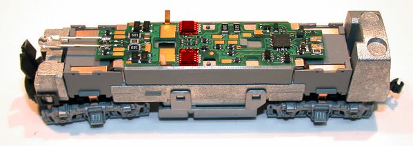
Good, it did. And this one, so they're both together
OK, now. Is there a pad or some sort of contact on the underside of the decoder that makes contact with those power pickup bars? The decoder must be getting it's power supply from those bars somewhere. And is the decoder otherwise insulated from the bars? In the top pic, There looks like there's 2 large brass pads on the decoder that those motor tabs might get bent down onto and soldered too. Is that so? It would be essential that for the DCC decoder to work that is has a power pickup from those bars, and that the motor tabs also have contact from a source on the decoder but insulated from those bars.
Now that I can see the bars you were talking about and those brass tabs from the motor sticking up, I've realised that what I thought were gaps and tabs on the decoder, were just the "kick-ups" in those bars/strips. Lets see if that photo copied and pastes
Good, it did. And this one, so they're both together
OK, now. Is there a pad or some sort of contact on the underside of the decoder that makes contact with those power pickup bars? The decoder must be getting it's power supply from those bars somewhere. And is the decoder otherwise insulated from the bars? In the top pic, There looks like there's 2 large brass pads on the decoder that those motor tabs might get bent down onto and soldered too. Is that so? It would be essential that for the DCC decoder to work that is has a power pickup from those bars, and that the motor tabs also have contact from a source on the decoder but insulated from those bars.
goscrewyourselves
I'm the one
Toot'n,
Can't put the screw up with the new engine to a beer or two, I just saw that it was an F7 and didn't realise what the "P" indicated or that it was longer. Bottom line, my screw up.
I have reset my iron to 550 F and am using a smallish chisel tip along with .32 solder with resin and flux. If that ends up being too hot, I can drop the temp in 1 F steps so, that too will be trial and error. I don't think the temp of the iron (750 F) was the cause for any issues as I soldered all of my other decoders in at that temp, BUT, only had to do the others once.
You got it now mate, exactly. The tabs you see sticking up are the "motor tabs", they get soldered to the pads on the decoder BUT are insulated from the engine body AND the brass rails (strips).
I believe there are some sort of contacts beneath the decoder that contact the two rails which contact the tabs coming up from the trucks/track power.
Can't put the screw up with the new engine to a beer or two, I just saw that it was an F7 and didn't realise what the "P" indicated or that it was longer. Bottom line, my screw up.
I have reset my iron to 550 F and am using a smallish chisel tip along with .32 solder with resin and flux. If that ends up being too hot, I can drop the temp in 1 F steps so, that too will be trial and error. I don't think the temp of the iron (750 F) was the cause for any issues as I soldered all of my other decoders in at that temp, BUT, only had to do the others once.
OK, now. Is there a pad or some sort of contact on the underside of the decoder that makes contact with those power pickup bars? The decoder must be getting it's power supply from those bars somewhere. And is the decoder otherwise insulated from the bars? In the top pic, There looks like there's 2 large brass pads on the decoder that those motor tabs might get bent down onto and soldered too. Is that so? It would be essential that for the DCC decoder to work that is has a power pickup from those bars, and that the motor tabs also have contact from a source on the decoder but insulated from those bars.
You got it now mate, exactly. The tabs you see sticking up are the "motor tabs", they get soldered to the pads on the decoder BUT are insulated from the engine body AND the brass rails (strips).
I believe there are some sort of contacts beneath the decoder that contact the two rails which contact the tabs coming up from the trucks/track power.
Last edited by a moderator:
Not being familiar myself with N scale circuitry and how they all go together put me at something of a disadvantage, but so long as those bars/strips are contacting the pickups on the decoder, then all should work as intended. It doesn't look as though there is any lighting board circuitry in N scale locos for DC, as HO would have had for some time now, where you have the choice of either plugging a DCC decoder in, as an easy method, or discarding the lighting board altogether and hard wiring the DCC one in to the lights and motor direct. A thing you usually do when installing sound decoders.
If the decoder you have already in the loco won't respond, but when replaced with the new one does, then you'll know it was definitely a dud.
That bar that has come off the plastic stud. Might be advisable to glue it down over it, it might, by being loose and raised, be pushing the decoder contacts, up and out of contact.
goscrewyourselves
I'm the one
Toot'n,
There really isn't such a big difference between N and HO scale when it come to decoders. This Kato engine comes with a factory fitted light board and DC as standard. The TCS decoder is a simple drop in type, no wires just a matter of removing the light board and dropping the DCC decoder in place over the rails and soldering the motor tabs to the appropriate pads on the decoder. That's it, very very easy.
The rails that you see that are raised are a "normal" issue with the Kato engines, I would prefer to see a better method for their installation, perhaps plastic clips that they slid under to keep them solidly in place BUT allow them to be removed so they can be insulated when installing a decoder. Anyway, when the decoder is located and the Motor Tabs soldered to it, that holds th decoder down which, in turn, pushes the rails down and back into their proper place. That in turn places pressure on the ends of the rails, forcing them down and onto the tabs from the trucks. Yep, it all looks a bit sloppy as seen above, but when put together it becomes quite solid.
At this stage, because the motor is free and the wheels all turn on DC, I am leaning toward it being a decoder issue. If things still do not work when the new decoder is installed OR the new decoder fries itself when power is applied then there is obviously some other issue. If that happens, and I hope like hell it doesn't, then I think that will be the sign to say good bye to that particular engine.
Anyway, I do have an F3 A with DCC installed (double checked this time) on its way to me and yes, the F3 shells/bodies and F7 shells/bodies are interchangeable according to Kato. I bought my wife an F3 A with DCC installed so I have also compared the two engines side by side and they are identicle in length and width.
goscrewyourselves
I'm the one
Okay, the new decoder arrived and has been installed. This is what is happening now:
Thought a picture was worth a thousand words. Looks to me as though it is a power problem, the engine etc is getting intermittent power instead of a steady flow? If I am right then the question now is, why?
Thought a picture was worth a thousand words. Looks to me as though it is a power problem, the engine etc is getting intermittent power instead of a steady flow? If I am right then the question now is, why?
