How to make a Control Panel?


This Control Panel thing has got me completely worked up to the point where I can't focus on any other part of the layout. Much of this evening has been "playing with" PSP 7 Pro trying to create something that replicates my track plan (specific to the turnouts/points) and that might be feasible and doable. This is what I have come up with:

AL1XioY.jpg


Okay, this is where you guys need to be critical - forget pathetic sensitivities and play "hard ball" with this.

My reasoning for what is seen then:

- the row of BLACK circles represent the Toggle Switches (DPDT)
- the GREEN "M" depicts the "Main Track" direction for the switch
- the RED "D" depicts the "Diverging Track (turnout) direction for the switch
- the numbers depict the specific "Turnout/Points" and are duplicated on the "track plan" as can be seen

- the green "DOTS" on the track plan depict the "LED's"

- the "P1/P2" represent the Passenger Lines
- the "S" represents the siding
- the "F1/F2" represents the Freight Line

What I am envisaging is when the "Switch" for "Turnout 1" (for example) is thrown for the "Main", the "GREEN LED/s" on the main will be illuminated/lit and the "GREEN LED" on the "TURNOUT" will be "OFF".

When the switch for turnout 1 is thrown for the diverging track (turnout) the "GREEN LED" in the turnout will be lit and the "GREEN LED" past the turnout on the "MAIN" will be "OFF". It would be better if that LED could go to "RED"

As said, be critical, play hard ball, to hell with sensitivities and so forth - tell me if this looks okay and if NOT what the problem/s are with it. If there is a better (easier) way to incorporate the LED's then say so, perhaps the double colored variety in red and green might work better, I don't know which is why I am asking.

Don't know if this is relevant or not but the size of the panel is 11" X 6.5" and does not incorporate the other 5 turnouts. I am going to need another panel for those and think I can put them all on the one panel, hopefully.

Now, on the "off chance" that this will work and there is nothing wrong with the theory, I will still need to figure out how to wire it all up - and that my friends for me, is going to be a nightmare :)

Anyway, hope this makes sense so balls in your court .........
 
Last edited by a moderator:
Have just found out that I have too many switches and LED's so ... is this better?

I0PSqxS.jpg


I'm sorry to be such a pain in the butt - I am trying to understand all of this.
 
Toot'n,

Thanks mate - now all I have to do is work out what I need and how to put it all together :) At least I have a pretty picture which is more than I had yesterday, so that's a bonus.
 
Consider this, at least you're working in DCC, not DC, where you would also need a DPDT direction switch for every track and insulating gaps at each end, wired so you could bring a train in from one end, with that tracks direction switch pointing in the incoming direction to do so. Then when leaving, flip it to the other direction, to continue. And by your diagram, if you wanted to cross over to one of the other tracks, put that track's direction switch facing the incoming train etc, etc. Why I gave up going to the club on DC only days, too many flippin' switches.
 
Just in case I've puzzled you there, yes the club's panels have those direction switches on them, but when running DCC, they all just get turned to the on position, doesn't matter in which direction, either or either to connect the whole layout.
 
Have just found out that I have too many switches and LED's so ... is this better?
Much better. Will work with the X16s (Cobolt Classic Omega), as is, without needing anything extra.

Taking your first diagram each one of the eight crossovers will just be a duplicate of that. Remembering of course that the LEDs will be reverse of each other.
TonyControlPanel.png
 
Last edited by a moderator:
Horseman,

Thanks for the confirmation and yep, quite possibly did misread something. Thanks also for the schematics, that will help a lot as well, that and with Ian's offer to talk me through things.
 
Received the first of my DCC Concept Cobalt Classic Point Machines today. Setting these things up is a breeze - literally 30 seconds from out of the box to being ready for installing. One fulcrum, one wire and one screw, that's it. The one thing I do like is how they come with a pre cut 1/8th" double sided tape that lets you hold the machine in place while putting in the screws. Even I can install these without any assistance.

The other thing I like is the fact there is no soldering required for wire attachment. It really couldn't be any easier.

The rest of the needed hardware arrives tomorrow and Friday. Those things being the DPDT micro switches, red/green LED's and 1000 ohm resistors. Once I have them, I can begin a "test install" on my "mock up Panel" below:

RRwPaTr.jpg


I am building the actual panel from 1/8th polystyrene from Plastruct, purchased from Klein's but who knows when it will arrive. I placed that order Monday afternoon and it is STILL being processed. Hopefully, I might see my "plastic" early next week - maybe!
 
I'm just catching up on your new adventure Tony, please post your step by step for this control panel. I operate my switches via hand control with the tortoise switches but did do some experimenting with green/red led as per which direction the turnout is facing and got it to work but that's about as far as I went but I am interested in doing a control panal as well.
 
Lynn,

What you did is pretty much what I want as well. The Panel is nothing more than a pretty addition to attach the Toggle Switches and LED's to.

The only thing that will be different from you is my use of DCC Concept Cobalt Point Motors instead of those other things. In a nutshell, I want to wire the Cobalt's to a Toggle Switch and have lights to show which way the points are thrown. I was told that if I use the Red/Green (all in one) LED then I could have one light Green for the Active or Open Track and the other/s light up Red for the inactive or closed Track. That is a nice option BUT I would settle for just Green LED's to to be lit to show which track is in use.

The toughest part for me is NOT knowing the terminology so when some one says do this or that using electronic terminology, they may as well be talking Arabic.

I repeat though, the Panel itself is nothing more than some where to put the Toggle Switches and the LED's and is easy (very easy) to make.

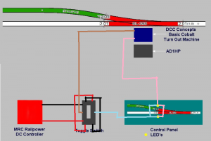
This is one diagram I found to wire it all up using the Bi Colored LED's and using 1 toggle switch to operate 2 turnouts so both changed to match the direction of travel with the flip of one Switch:

FCQ8yH8.jpg


I was prepared to use one Toggle Switch per Turnout/Points Motor and LED's for that turnout. Apparently that isn't necessary.

The only thing I want to add, between the Power Source (MRC Railpower 1370 DC Controller) and the Switches and LED's, to the above schematic is a 24 Post Terminal Block so I can wire everything else up without having to splice wires into a secondary DC Bus.

So, with the above schematic in mind, this is what I have bought:

100 X LED GRN/RED DIFF 3MM ROUND T/H
20 X DPDT ON/ON Mini Toggle Switches
200 X 1000 ohm 1/4 watt Resistors
 
Last edited by a moderator:
AAAAHHH! I see your problem there Tony. You're using the wrong language to translate from. Swahili is the one you want. All the electronics people use that.
 
Tony,

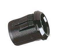
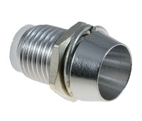
You will also want to order something like this: http://www.taydaelectronics.com/3mm-bezel-led-panel-mounting-clip.html for mounting the LEDs to your panel material. They come in a couple of different styles: one piece that presses into the panel and two piece, threaded with a nut so they mount the same as a switch. They also come is several colors - black, white, chrome, etc. Just search for '3mm led panel mounting clip'. I prefer the two piece, which are actually 3 piece - the have a small insulator the plugs into the back of the mount. They attach securely to the panel.

PS: I've ordered lots of parts from Tayda and am pleased with the quality and prompt shipping.

ikiwa unahitaji msaada, tu uulize.
 

Attachments

  • 1 piece.jpg
    1 piece.jpg
    11.7 KB · Views: 207
  • 2 piece.jpg
    2 piece.jpg
    9.5 KB · Views: 207
Last edited by a moderator:
The only thing that will be different from you is my use of DCC Concept Cobalt Point Motors instead of those other things. In a nutshell, I want to wire the Cobalt's to a Toggle Switch and have lights to show which way the points are thrown. I was told that if I use the Red/Green (all in one) LED then I could have one light Green for the Active or Open Track and the other/s light up Red for the inactive or closed Track.
Yup the only real difference is the type of LED. Do you still want only the "through" rough lighted? I gather not from the parts list given.

This is one diagram I found to wire it all up using the Bi Colored LED's and using 1 toggle switch to operate 2 turnouts so both changed to match the direction of travel with the flip of one Switch:
Even they are making it harder than it needs to be. If the LEDs are put in series with the turnout motors there do not need to be any resistors. The motor IS then the resistor. The only reason I can see to do it the way they have shown is if they were having brightness (or dimness) issues with their specific LEDs, or if they just want to sell resistors.

was prepared to use one Toggle Switch per Turnout/Points Motor and LED's for that turnout. Apparently that isn't necessary.
Nope, one toggle per crossover is all that is needed. One motor, two motor, it doesn't matter since they draw so little current. You could add another couple for activating semaphore signals. I've used one toggle for a double crossover.
 
Last edited by a moderator:
Kevin,

Tony,

You will also want to order something like this: http://www.taydaelectronics.com/3mm-bezel-led-panel-mounting-clip.html for mounting the LEDs to your panel material. They come in a couple of different styles: one piece that presses into the panel and two piece, threaded with a nut so they mount the same as a switch. They also come is several colors - black, white, chrome, etc. Just search for '3mm led panel mounting clip'. I prefer the two piece, which are actually 3 piece - the have a small insulator the plugs into the back of the mount. They attach securely to the panel.

PS: I've ordered lots of parts from Tayda and am pleased with the quality and prompt shipping.

ikiwa unahitaji msaada, tu uulize.


Thanks for the link and suggestion, it sounds good and will finish the look of the panel nicely. I'll order a bunch today.

Oh, and while I think about it: why 100 LEDs and 200 resistors?

Okay, good question with the short answer being ... be buggered if I know?" I was working on 20 turnouts X 3 LED's per turnout with some spares just in case. Buying 100 of them wasn't much more than buying 60 so that's why I got the 100. Fact of the matter is I only need 3 LED's per 2 turnouts (as per the schematic) so I have really over bought them, that's for sure.

Same thing (more or less) with the resistors, although I will most likely also use them for my structure lighting as well. At 3 cents per resistor, I bought what I was gong to need and what I might need down the track.
 
Yup the only real difference is the type of LED. Do you still want only the "through" rough lighted? I gather not from the parts list given.

Even they are making it harder than it needs to be. If the LEDs are put in series with the turnout motors there do not need to be any resistors. The motor IS then the resistor. The only reason I can see to do it the way they have shown is if they were having brightness (or dimness) issues with their specific LEDs, or if they just want to sell resistors.

Nope, one toggle per crossover is all that is needed. One motor, two motor, it doesn't matter since they draw so little current. You could add another couple for activating semaphore signals. I've used one toggle for a double crossover.

Horseman,

Thanks for the info and heads up. Mate, if there is an easier way to do this I would be more than interested. As of today I have everything I "thought" I needed to put this Panel together.

In so far as the lighting goes - I was led to believe that if I used the LED's I have as per the wiring diagram, the active (through) track would light Green and the inactive (closed track) would light Red. I take it that you don't think that will happen with what I have.

Before I say this I want to explain my terminology ... the "active track" is the one the train will be running on. The "inactive track" is the track that the train wont be running on, the track where the points haven't be thrown. In short - one of the following options:

AIwKxIp.jpg


c616sdl.jpg


One of the above is what I am wanting. If the wiring diagram I posted isn't right for one of these options then please tell me what IS needed. Feel free to change the diagram I posted as I will understand a picture far better than I will an explanation.

If what I have bought is not right or needed, please tell me that as well along with what I DO need.

Thanks guys and I know I am being hard to get on with but I am clueless when it comes to these things and need very little, baby step explanation/s pictures that clearly show me how I can build this thing. I have built structure lighting panels without a hitch and really thought this would be similar to do, but I was evidently wrong with that assumption.


Back
Top