KB02
Well-Known Member
Well it's been long enough for my empire to remain stagnant. Time for an expansion.
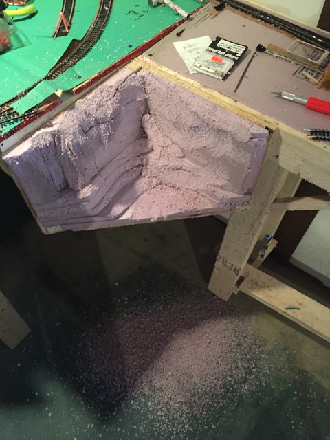
The Western wall of the basement bar is the next stretch to cover. BUT, since that is also the wall the seems to have the most water intrusion, I was skeptical of building there. But then I thought that if I built it modular style, I could just move the whole section if I needed to. So that became the plan. This expansion is simply going to be a staging yard for now, but may turn into a town or industry in the future. I'm building it out of a 2x4 frame with foam top.
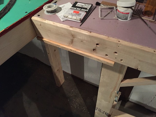
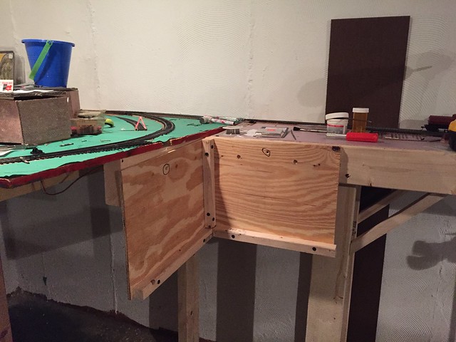
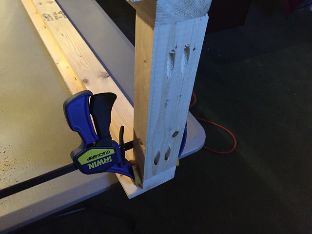
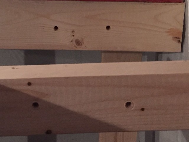
Starting with the runners. It's an 8' 2x4 with a 1x1 section cut out to hold the foam:
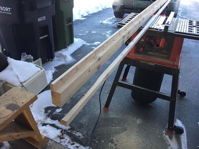
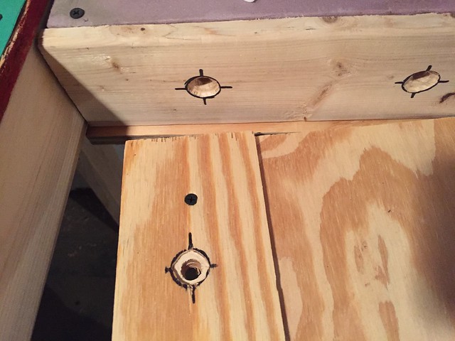
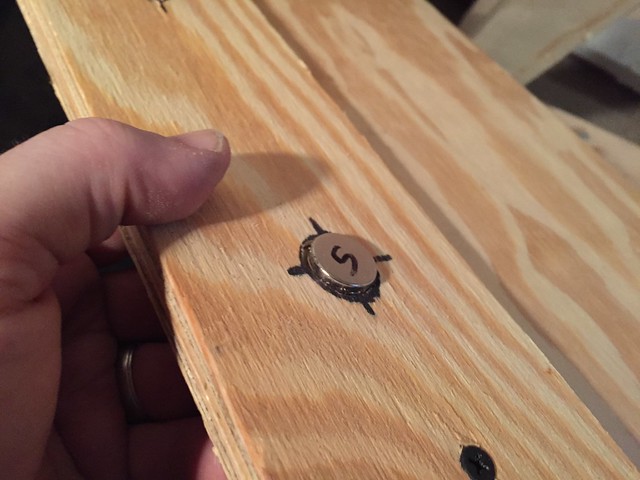
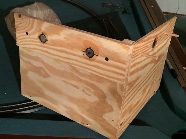
A shortened section of 2x4 caps off the ends making it only about a foot wide. Used a jig to french in the screws to keep it clean looking:
The 1x1 section cut out of the runner was used to make a ladder type configuration for the base. Mainly to help with strength as I am only using 1" foam.
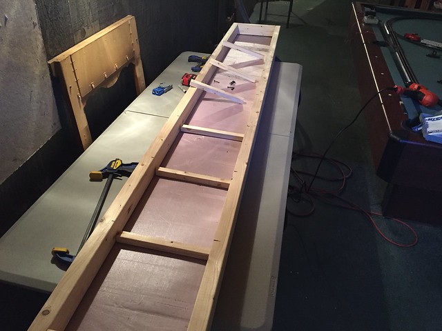
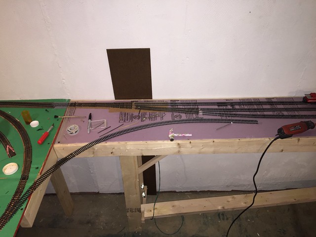
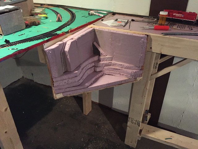
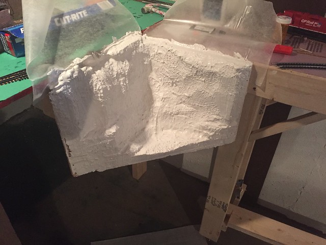
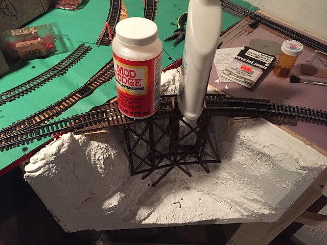
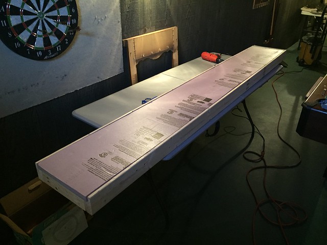
Foam in place:
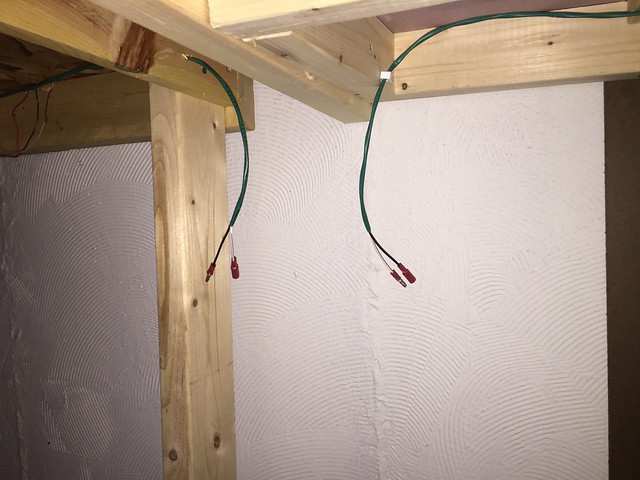
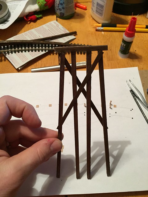
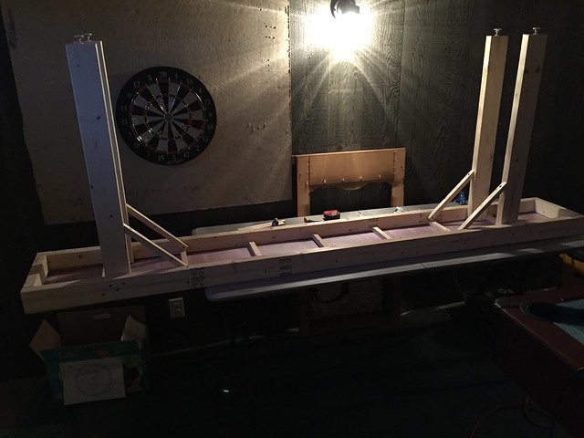
Legs in place (with adjustable feet to help with leveling):
AND...
well... at this point I should confess that I broke the most sacred of bench work building rules... I didn't bring my wood inside and let it acclimate to the area where is it going to be before I started building. I ended up with a pretty warped tabletop when it was all together. And it's not like it was a simple, easy to correct warp either. At only 1 foot wide, there ended up being about a 3/4" difference in height from one side to the other. I installed a cross bar on the bottom of the legs to try and hold it straight. I've got the height difference down to about 1/8". I'm happy enough with that to keep moving on the project.
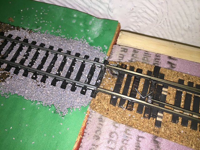
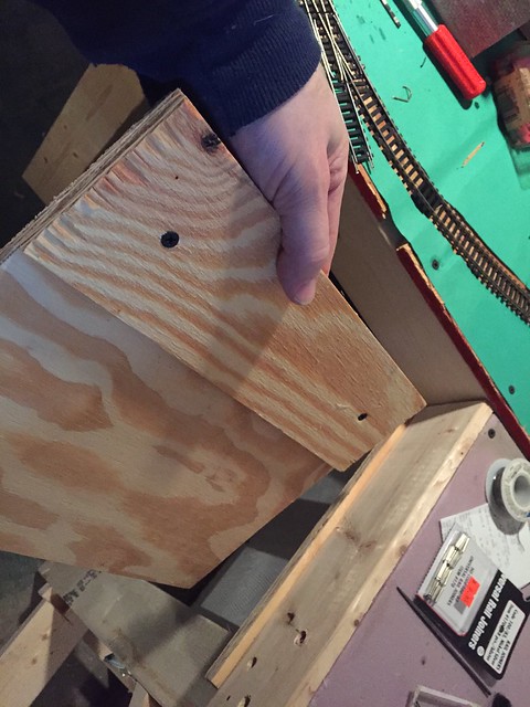
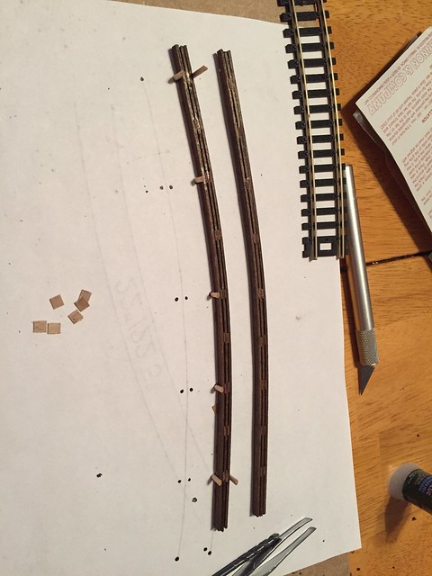
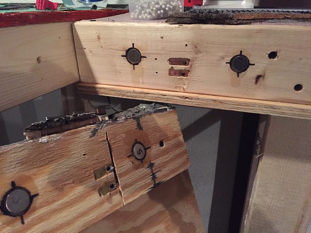
Drilled a couple of 1/4" holes to hold some locating dowels:
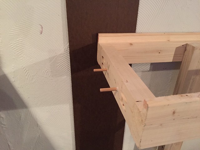
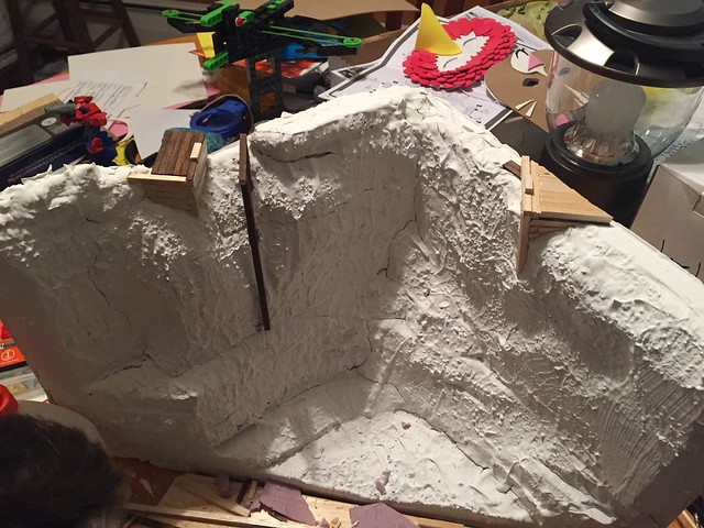
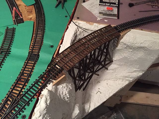
And then put it all in place:
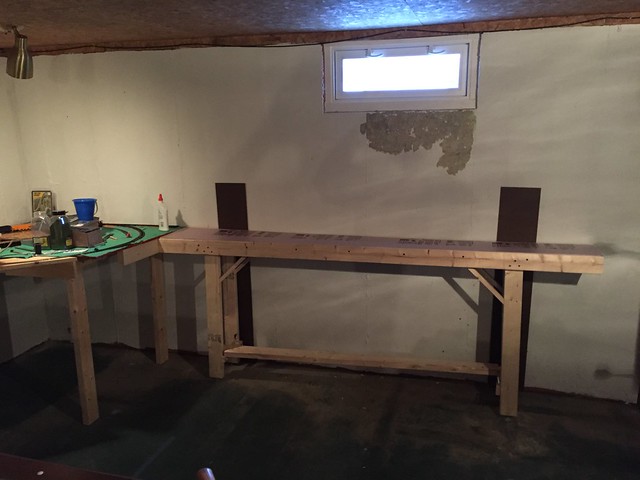
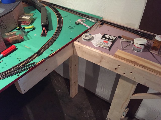
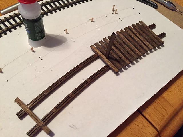
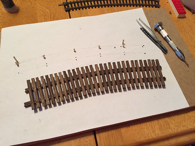
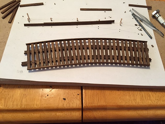
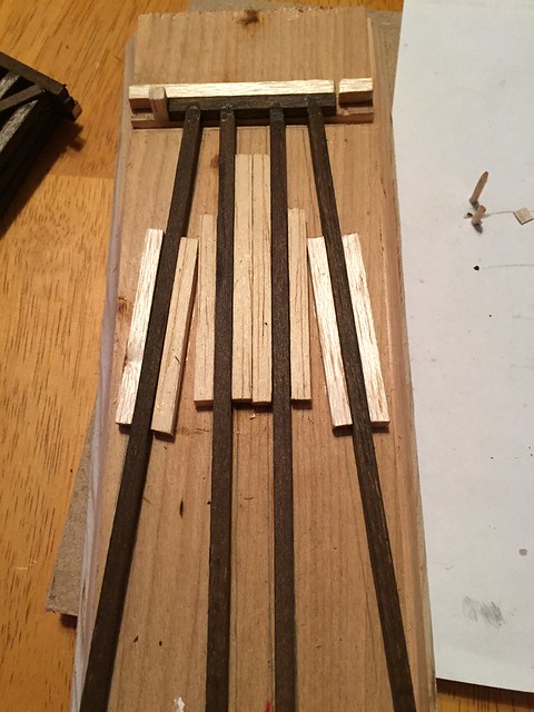
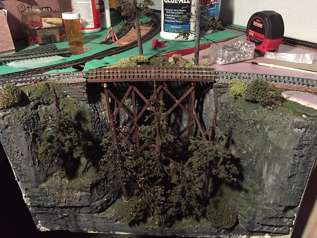
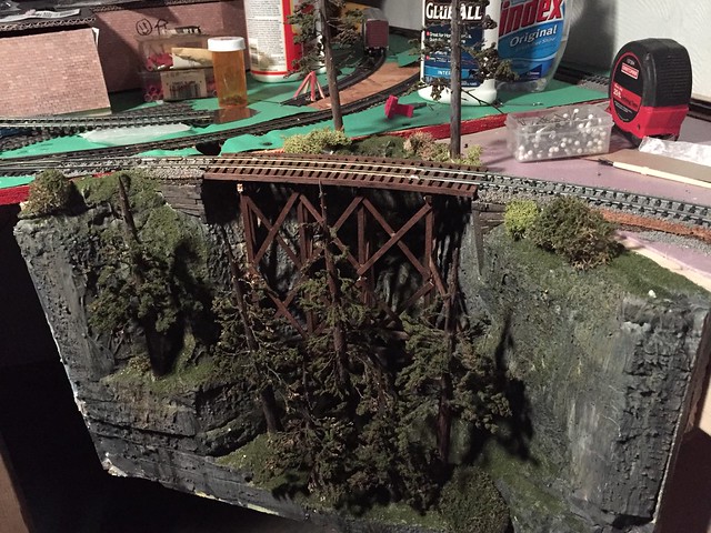
The photo makes the warp looks worse. The benchwork on the left is actually slanted towards the wall (intentional design), and the new section is slanted slight away from the wall (the UN-intended effect). With custom, hand built, turn outs on the right and bottom of the curve, trains will be able to enter from either direction.
Well, that's where it's at for now. I'm gearing up for a trip to Springfield, MA for the train show in a couple weeks. Anyone else headed that way?
The Western wall of the basement bar is the next stretch to cover. BUT, since that is also the wall the seems to have the most water intrusion, I was skeptical of building there. But then I thought that if I built it modular style, I could just move the whole section if I needed to. So that became the plan. This expansion is simply going to be a staging yard for now, but may turn into a town or industry in the future. I'm building it out of a 2x4 frame with foam top.
Starting with the runners. It's an 8' 2x4 with a 1x1 section cut out to hold the foam:
A shortened section of 2x4 caps off the ends making it only about a foot wide. Used a jig to french in the screws to keep it clean looking:
The 1x1 section cut out of the runner was used to make a ladder type configuration for the base. Mainly to help with strength as I am only using 1" foam.
Foam in place:
Legs in place (with adjustable feet to help with leveling):
AND...
well... at this point I should confess that I broke the most sacred of bench work building rules... I didn't bring my wood inside and let it acclimate to the area where is it going to be before I started building. I ended up with a pretty warped tabletop when it was all together. And it's not like it was a simple, easy to correct warp either. At only 1 foot wide, there ended up being about a 3/4" difference in height from one side to the other. I installed a cross bar on the bottom of the legs to try and hold it straight. I've got the height difference down to about 1/8". I'm happy enough with that to keep moving on the project.
Drilled a couple of 1/4" holes to hold some locating dowels:
And then put it all in place:
The photo makes the warp looks worse. The benchwork on the left is actually slanted towards the wall (intentional design), and the new section is slanted slight away from the wall (the UN-intended effect). With custom, hand built, turn outs on the right and bottom of the curve, trains will be able to enter from either direction.
Well, that's where it's at for now. I'm gearing up for a trip to Springfield, MA for the train show in a couple weeks. Anyone else headed that way?