DCC Wiring Advice Needed...


jb7778

New Member
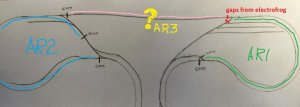
Getting close to having my layout finalized.. Looking for recommendations how to isolate my reversing sections. Below Ive identified where I initially located GAPS, then I added the crossover in the peninsula and the re-entrance in the left side crossover. Uncertain where additional gaps are necessary. Any advice where to specifically locate so all bases are covered?

Background: HO Scale/DCC/Peco Electrofrog w/PL10&13 switches everywhere but 3 insulfrogs curved turnouts, 2 on left, one on right/ Usually one train in use but occasionally 2, the second operator is 9yrs old/ Modern Diesel locos

To put into perspective it is 14' between turnouts on back mainline and 32' end to end bench work

Let me know if any other info is needed.. Any feedback greatly appreciated, thanks in advance!!

ATTACH]
 
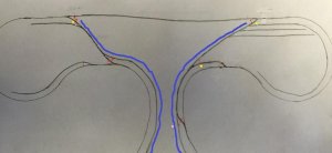
For starters there need to be a whole lot of insulated joiners or gaps just for the electrofrog turnouts. I've marked those with the red dots. If you also add feeders to each of the spurs there need to be more insulated joiners or gaps. I've marked those with the pale blue dots.

As for the reversing issues, what you proposed would probably work but it would be a bit strange. I always try to make the largest, longest run possible with no gaps. In this case that would be the entire outside loop. The way the back track drops into the front loop is a bit odd and there are many ways that it could be wired. I think the simplest is to make that entire swoop into the reversing section (the dark blue line), with the additional (in addition to those needed for the electrofrog) gaps marked in yellow. This way only one auto reverser is needed BUT only 1 train could be in that entire section at a time. So it might be better to break that again at the crossover to the center right. An additional insulated joiner/gap would be required (pink dot) and an additional auto reverser.
wgaps.jpg

As I said this is just one possible way to do it.

P.S. Well, the pale blue dots don't show up very good.
 
Last edited by a moderator:
Thanks for the response Horseman... I have accounted for and have insulated rail joiners on all the powered frogs accordingly. I also already have 2 Digitrax AR1 reversers in my possession so prepared for 2 loops.

Confused why I would need additional GAPS at the spurs if powered, this would only be if the outer loop/mainline was the reversing section?

Any recommendations if the loop at each end was isolated like initially proposed? The loops/distance between gaps is longer than any trains Ill be running...
 
Confused why I would need additional GAPS at the spurs if powered,
feeders on the spurs would put power backwards into the frog and cause a short.

Any recommendations if the loop at each end was isolated like initially proposed? The loops/distance between gaps is longer than any trains Ill be running...
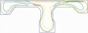
You were wanting to make either side a loop, as in the green in the picture below.
That would work if you moved the gaps on the very upper right (near the end of the yard ladder) to the other side of the turnout.
Even then you would run into the same issues that we just discussed on another thread where the layout is wired as a double track main with a loop at either side. Also there is that pink track. That combined with the red section actually forms another larger reversing loop shown in yellow. The more tricky part is that larger reversing loop contains portions of both of the other reversing loops. I'm thinking that if you wire the pink as a main track, it will further complicate the case as discussed in the other thread, or that you would need a third reverser on that pink track. A third reverser is also tricky as that would be a reverser off of two reverser sections.

As I said on the other thread and implied here, when using auto reversers I attempt to let them be in a relaxed state most of the time. Only seldom would they need to activate. The two loops on the end of a double main line has them constantly changing.

(And yes I know that "relaxed" is only a metaphor with the 100% electronic ones).
Gaps Take2.jpg

The other thread http://www.modelrailroadforums.com/forum/showthread.php?38673-Auto-reverse-module-(DCC)-Questions
 
Last edited by a moderator:
Normally I just try to answer the question being asked and try not to rabbit trail, but can I ask what is the concept behind this design? I've been conceptualizing running trains on it and not coming up with any scheme. Even with all that track it seems hard to run two trains except as elephant style following one another around the same route. I am seeing only one passing siding and even that is "the other side" of the dog bone. When running as loop to loop the yard ladder is on the main line. I am assuming I am just missing some "duh" thing that I've been blinded to while working on the wires.
 
Your not missing anything, Im not sure there is a concept and Im not familiar with prototypical operations. My initial goal was to have long continuous run for my nine year old and i to run trains with some operations serving Industry... I foresee the train primary traveling around the outer loop over and over, the loops with allow him/us to turn around when board and go the other direction. Also envisioned being able to run 2 trains opposite direction as long as one, likely mine, uses the inner passing and times it until the other passes? I was born, raised and work in agriculture, excited for modeling and scenery with an AG theme... Scenery with trains more than trains with scenery if that makes sense. At the same time I want to minimize potential issues, frustration and do it as right as I can the first time.

As far as my GAPS/isolation, you mention the need for the gaps on the upper right turnout on the opposite side... I was just evaluating and realize it is naturally gaped from the 2 electrofrogs meeting there... So for my simple mind, If I were to stick with 2 loops on the ends what additional isolation is required for the original diagram? The third reversing unit lost me Thanks Again
 
As far as my GAPS/isolation, you mention the need for the gaps on the upper right turnout on the opposite side... I was just evaluating and realize it is naturally gaped from the 2 electrofrogs meeting there...
Yeay!

So for my simple mind, If I were to stick with 2 loops on the ends what additional isolation is required for the original diagram? The third reversing unit lost me
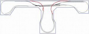
None, I don't think. You can wire the pink line directly as a main and see what happens. While an AR looks good in theory, I don't like the idea of it passing into another AR section.
more-loops.jpg
 
My initial goal was to have long continuous run for my nine year old and i to run trains with some operations serving Industry... I foresee the train primary traveling around the outer loop over and over, the loops with allow him/us to turn around when board and go the other direction. Also envisioned being able to run 2 trains opposite direction as long as one, likely mine, uses the inner passing and times it until the other passes?
Yes, that would work. The general rule is one passing siding for each simultaneously running train. So one train into the siding while the other passes.

Are you adverse to having grades? Seems like there is lots of room for two passing sidings, so both engineers could keep moving.
two_passing sidings.png
 
Not adverse to grades, the whole left half is a 2% WS kit leading to a 30" curved bridge over a large ravine in the left loop.. We started the layout in December of 2014, Im pretty well married to it now!! Have been back and forth between track work/modeling/scenery/studying/cussing when I get frustrated, I switch directions until I figure it.. Committed to my scenery/industry locations also... River/Bridges/Grain Elevator/Ethanol Plant should all be accommodated nicely
Ill get a few more recent pics posted first chance.... Posting pics and such is still kind of a crap shoot for me, I figure it out and forget how before I do it again! Appreciate your insights!


Back
Top