Orange Irish
Member
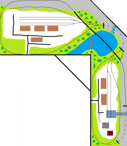
Anything to do with wiring is, so far, my weak point by far. On DCC, the attachment hopefully shows a basic layout (dogbone in an "L" that loops under itself in the middle), two 6x10 sections connected by an angled piece in the middle. The addition will be a reverse loop on each end, with turnouts inside each loop. If I wire an auto reverse module on each side correctly, will I have to do anything different to accommodate the turnout sections inside the loops?
Will standard bus wiring adequately power the layout...one bus wire with feeders every 4-5 ft or so, with one 5 amp booster in the middle, or divide the layout in half and power each side independently with a 5 amp booster for each side? A general estimate of track footage is about 100 ft. I'm not counting most of the sidings because I plan to back the locos in and won't need all of each section to be powered.
If anyone is nice enough to answer, keep in mind I'm an electrical novice and may require a 17 page diagram to understand it. Thanks!!