Scratch-bashing a B&O I-5d wood-sided caboose


IronBeltKen

Lazy Daydreamer
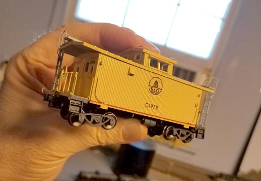
To some people, model railroading is an addiction; in my case, kitbashing/scratchbuilding is my “Drug of Choice.” No matter what project I may have planned, if I see an unexpected opportunity to create a home-grown model of something I’ve always wanted, I go for it! Everything else gets put on hold.

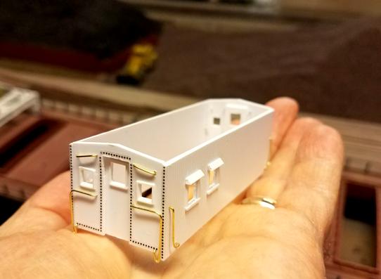
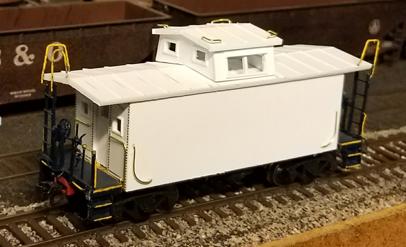
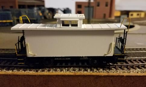
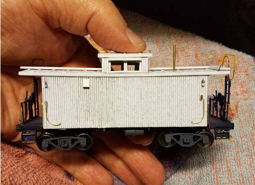
This HO scale rendition of a B&O I-5d caboose may seem totally unnecessary. After all, Spring Mills Depot announced a run of I-5’s and - if their past models are any indication - these will be very high quality and incredibly detailed. I ordered a few of them in January 2014 and who knows, they may show up any day now. But I’ve really been wanting to try scratch building one of these long before Spring Mills made their announcement. And when I noticed that the distance between the bolsters on an old worn-out brass I-12 was 19 scale feet – same as an I-5d – I realized that I might actually be able to build one using the brass I-12 chassis and some Evergreen styrene.

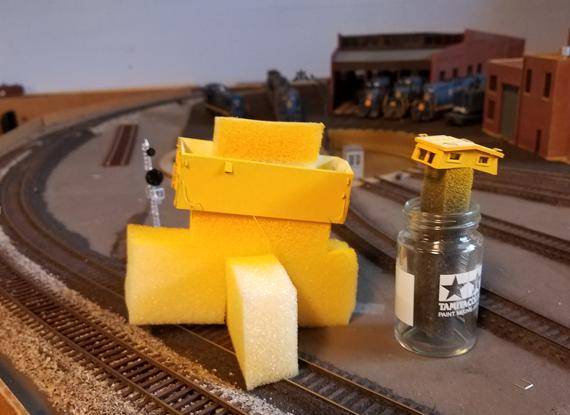
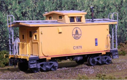
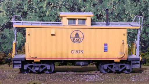
Since I’m modeling a line that runs near Cleveland, I wanted to model one of the many [C&O] yellow cabooses painted by a few of the shops in Ohio. I perused the rr-fallenflags.org collection of B&O rolling stock photos and found this one by Dan Dover: http://rr-fallenflags.org/bo/bo-c1979abp.jpg
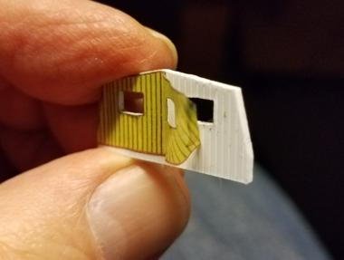
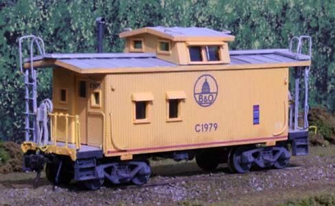
C1979 had the exact same body style as the red ones I often saw in Maryland during the train-chasing days of my youth, i.e., no windows on the side with the stove. [I didn’t learn until later that all I-5d’s of this type had at least two windows on the opposite side.]

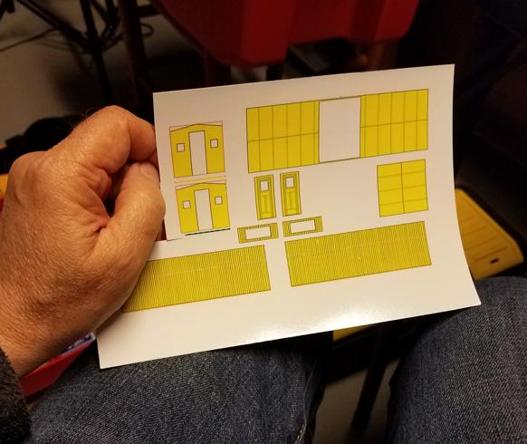
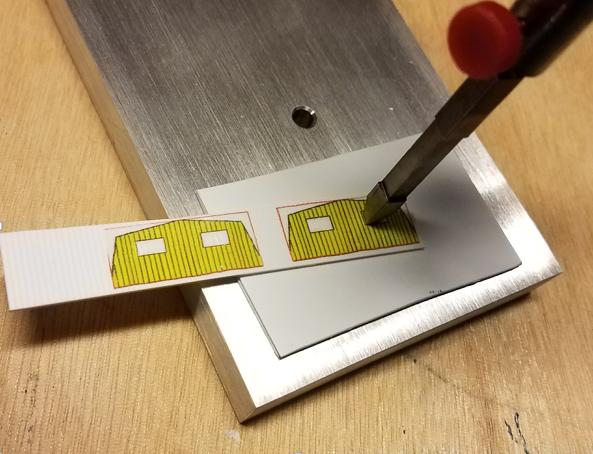
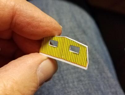
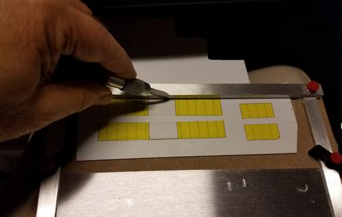
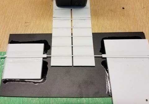
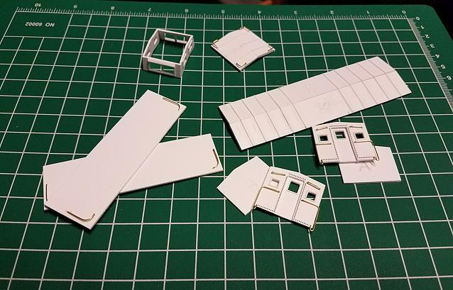
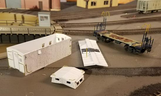
My first task was to locate some design drawings that I could scale-down to 1:87; a Google search led me to a site that had exactly what I needed. I don’t want to display those drawings here since they may be copyrighted; but I can show you the templates that I created from them:

001_PreliminaryDrawings.gif


The green-and-blue lines in the drawing represent one-inch segments that I used for sizing the image to exactly 1:87 scale.

(to be continued...)
 
My plan was to create decals from the above set of drawings to use as cutting templates. First, however, I needed to order a few tools from Micro-Mark to make the job a little easier. Among these were a Press-It® arbor/punch press, a styrene sheet cutting jig, a new NWSL Chopper® to replace my old worn-out unit, and a 3/16-inch 90-degree corner punch bit.

002_CornerPuncherBitAsDelivered.jpg


When my Micro-Mark order arrived, I discovered that my corner-cutting bit was a tad oversized for the cupola end windows. No problem - I would simply use my Dremel to mill down each of the sides:

004_CornerPuncherBitBeforeMilling.jpg


003_CornerPuncherBitAfterMilling.jpg


...this gave me the exact-sized corner punching bit that I needed!
 
It seems like quite an undertaking, but you seem to have things planned out. Waiting to see the build.
 
AGREE with Chet - With all those "tools" from Micro-Mark - they must have loved you! Did you get a kiss with the order?

Looking forward to watching this!
 
As soon as I had verified the correct dimensions of the corner-punch blades on a plain paper-printed drawing, I went ahead and printed the template decals. Here is a photo of the sheet after I had already cut out the cupola end wall profiles:

005_SheetOfHome-PrintedTemplateDecals.jpg


First thing I did was put the cupola end wall decals on a piece of Evergreen V-grooved sheet styrene. I applied Micro-Sol just as if I were applying regular decals to a painted surface, because I wanted to prevent them from being pulled loose during the hole punching or cutting process. [I knew they could still be peeled off of the unpainted plastic later on.]

I punched-out the window holes first, in order to avoid the risk of pressing too near the edge and causing a tear:

007_PunchingOutCupolaEndWindows.jpg


I was quite pleased with the results, although I still needed to do a bit of precision filing to get the window edges smoothed-out and properly aligned. Once all the windows were done, I used a dedicated set of shears [for plastic cutting only] to cut trim off any sheet styrene that didn't look like cupola end walls:

009_CupolaEndWallFullyCutOut.jpg


...and the template decals peeled right off when I was finished with them:

010_PeelingOffTemplateDecal.jpg


I followed this same general process for the cabin end walls and the left side wall with the two windows in it.

One thing I wanted to do before gluing any of the pieces to each other, was to drill the holes for the grab irons. That is much easier to do with a flat piece of plastic on a hard surface! I used K&S .020" diameter brass wire for the grabs themselves. I never got around to photographing this particular task since I was too busy struggling to get the wire pieces bent in the correct shapes.
 
... With all those "tools" from Micro-Mark - they must have loved you! Did you get a kiss with the order? ...
No, Sherrell, only a handshake! To qualify for a kiss, I would've had to get a laser cutting machine. But that's beyond the limits of my budget...
 
No, Sherrell, only a handshake! To qualify for a kiss, I would've had to get a laser cutting machine. But that's beyond the limits of my budget...

Ahhhh - Spoken like a 'true" Model Railroader! LOL

Hear I am approaching 3/4 of a century and you have already taught me 3 things about scratch building that I did not know; and I used to do a whole bunch of it!
Thank you.

(This is going to rate a telephone call later at another date; besides, I want to hear how our "future aviator" is doing?)
 
Last edited by a moderator:
Another thing I did that I unfortunately did not photo-document, was when I used my Chopper to cut lengths of .015"x.030" Evergreen strips to simulate the outside frames of the windows. This was easily done by using the tip of a "push" needle to apply microscopic amounts of Testors Model Master glue along each window edge, then carefully laying the piece of strip over it. The Model Master cement set slowly enough to give me a few seconds to reposition the strip as needed. It took a few evenings to get all the windows framed.

Next, I applied Micro-Mark 3-D rivet decals to the end walls, along the outside edges and over the door openings, to match the patterns visible in the various photos I studied. [The ends and the roof were the only parts of the caboose body made of metal rather than wood.] Luckily one of my local modeler friends had a nearly-full sheet he could lend me, so I didn't have to spend another $18 buying a sheet from Micro-Mark!

Now that I had my wall panels done [or so I thought...], I turned my attention to fabricating the roof sections - two long pieces for the cabin and two short ones for the cupola. Once again, I applied some template decals to use as cutting guides:

010a_TemplateDecalsAsCuttingGuide.jpg


The Dupli-Cutter jig saved me quite a bit of time cutting the sheet styrene components, but the results were nowhere near 100% perfect IMHO. There is absolutely no way that a score-and-break cut edge can ever match the precision of a laser cutting machine, the type which guys like Pelle Soeborg and Bernie Kempinski use to build the spectacular models they write about in MR. Furthermore, I noticed that after making a few cuts, the lockable guide bar started getting worn down along the bottom; the soft aluminum was no match for the hard steel of the Xacto blade repeatedly scraping against it. NWSL should have made it out of steel or some other stronger metal, now I can no longer be certain of getting a perfectly straight cut whenever I use it.:mad:

Anyhoo...the cabin roof template decals in the photo show wide openings in the center where the cupola is supposed to fit. Then I became concerned that if I did cut away the roof as shown, it would compromise the structural rigidity of the styrene. So I adopted 'Plan B', which was to leave the roof halves solid and make angular cuts along the bottoms of the cupola end walls to match the contour of the cabin roof.

One more thing I needed to do was add the simulated sheet metal "seams", or bulges, to the roof. Evergreen does not carry the type of styrene "sheet metal" with the seams spaced the exact distance apart from each other; one size has them too close together, the next has them too far apart. Time to improvise.

I found that carefully-placed lengths of .030" x .030" styrene strip would give me the effect I wanted. The trick was to get them positioned perfectly flat on the roof sheets at the precise intervals to match an I-5d caboose roof. My solution was to construct a jig that would hold the strips in the needed position whereupon I would douse them with PlasticWeld:

010b_StringingRoofSheetMetalSeams.jpg


A paperweight held the roof halves parallel to each other while I positioned the strips over them. As soon as the cement was dry, I snipped off the strips along the inner and outer roof panel edges. I followed a similar routine to apply the seams to the cupola roof.

Finally, I was done with all the prep work on the wall and roof sections. Now they were ready to be cemented together:

011_PiecesBeforeCementingTogether.jpg


[I had already done the cupola sides before I remembered to shoot this photo...:rolleyes:]
 
Looks like this project was a waste of time after all! It was excluded from the list of photos of models exhibited at the RPM East conference last weekend. I had a bad feeling it wouldn't measure up to today's standards... **sigh**
 
That's really too bad! From what I have seen, it looks awfully good- precision - type work.
It is still something you can be proud of.
 
In my most recent blog entry, I mentioned that I had all the body pieces fully "dressed" and ready for assembly. Pretty close to the finish line, right? Well not exactly...

The brass chassis I was using was totally stripped down, i.e., the end platforms had been removed so I could more easily test-fit the body on it. Early in the project, before I had drilled any holes for the grab irons, I temporarily held the side walls to the end walls with scotch tape to determine where I should cut the bottom edge. I wanted the side walls to just slightly cover the sides of the brass frame, extending roughly 1/32nd of an inch past the bottom edges of the end walls [which sat directly on the frame]. I got my measurements and cut accordingly, drilled holes for the grabs and installed them; then I refitted the wall pieces together and did another test fit, and it appeared to be just right.

Fast forward to 10 days later, after the window strips and other details had been added. First I cemented the body walls together:

013_Body_walls_glued_together.jpg


...then I reattached the end platforms to the chassis, fit the body over the chassis and...uh-oh! I had totally forgotten that the end wall bottom edges would rest on the platform surfaces, not directly on the chassis as I had been assuming.:mad: Now the bottoms of the side walls didn't go far enough down to cover the chassis edge.

My first thought was to cut two extremely narrow strips of Evergreen grooved sheet and cement those to the bottom edges of the side walls. I succeeded in getting the grooved strips cut, fitted flush with the wall bottoms, and the grooves directly lined up on the adjoining pieces. I doused the joints with PlasticWeld and test-fitted the body with the extended wall sides, and...they covered the chassis alright, but they looked like hell! The bottoms of the 'J' grabs were now 12 scale inches up from the bottom edges.

So I wound up making 2 completely new side walls, which entailed cutting-in and detailing the two windows on the left-hand side, plus shaping four new slightly-longer 'J' grabs and drilling holes for them. It was an entire weekend's worth of work, but now at least I had properly-sized side walls that covered the chassis.

My roof halves were glued together, then I fitted them loosely on top of the body and the cupola. This was frustrating because every time I went to adjust the cupola position, its roof was pushed out of alignment...and vice-versa. I got the subassemblies positioned as close to "correct" as possible, and discovered the following:

014_CupolaTooTall.jpg


1) The cupola was too tall, and:

015_ExcessiveRoofOverhang.jpg


2) ...the roof was too wide!

I had to gently break-apart the cupola walls, trim them down, and re-fit them to each other. Fixing the roof problem was much easier - I just needed to shave-down the outer edges a little bit.

At this point, I glued little guide pieces to the underside of the roof and the top center position where the cupola was supposed to sit. This ensured that I could remove these pieces, then simply snap them back together in their correct positions. I shot this photo of the unpainted model while I had all the pieces temporarily assembled:

017a_FinalTestAssemblyBeforePainting.jpg


(OMG, that's some serious lens distortion with my cell phone camera - the roof didn't really sag that badly!:eek:)
 
I'm glad that you persisted and continued with the project. It looks really good. I don't think many people would notice small discrepancies but then I'm sure you would.

Nice work, keep posting.
 
After my bird-in-the-hand photo shoot, I disassembled the model and got the separate sections ready for painting:

017_SubAssembliesReadyForPaint.jpg


This meant getting all my air brushing paraphernalia ready, which is no small task for someone who lacks a workshop with a built-in spray booth. I likely spend more time setting up and cleaning up than I do actually spraying. I’ll often go to great lengths to avoid airbrushing if a hand brush can do the job; but this was not one of those times.

Since I have plenty of surplus rubber packing foam at my disposal, I cut up a few pieces to make holding jigs for the items I was painting [the body and the cupola]. This enabled me to avoid touching the pieces by hand:

018_FoamJigsUsedForAirBrushing.jpg


While the paint was curing, I printed up some decals – the 38” diameter B&O Kuhler-style Capitol Dome logo, the road number “C1979” for the sides and ends, and the red stripe that runs along the bottom. I covered the trucks and underside in a home-grown mixture of Tamiya “grimy black” since the PollyScale stuff is no longer available.

After applying the decals and a thin layer of dullcote, I snapped it back together for one quick photo:

018a_FreshlyPaintedAndDecaled.jpg


I didn’t want it to run it on my layout looking fresh from the paint shop [or a blue box]. The prototype was faded from years in the sunlight and repeated rain drenches, and I couldn’t install the window glazing until I finished with the “bleaching” process - airbrushing a thin coat of diluted flat white over the body. So I wasted no time disassembling it once more to apply the white wash.

Once I was satisfied with the level of fading, I installed the window glazing of Evergreen Clear sheet. I cemented it with Elmers [to avoid crazing or fogging the “glass”].

I attempted several times to shoot some indoor photos with my cell phone camera, but it just couldn’t seem to capture the faded look that my eyes were able to detect – the yellow always appeared too “lemony” and vivid. So I waited for my first opportunity to get some outdoor shots under direct sunlight. I dragged out the old photo-staging diorama and snapped a dozen images with my Canon Rebel, and here are my favorite ones:

019_I-5d_completed_32s.jpg


020_I-5d_completed_33s.jpg


021_I-5d_completed_34s.jpg


One final disclaimer: I never intended this to be a contest caliber model that rivals a factory-built Athearn Genesis or Tangent model. It just needs to look ok from a 2-foot viewing distance, like the many 30-year-old Athearn Blue Box cars that still roam my rails. Once the two Spring Mills Depot I-5d models that I ordered in 2014 finally arrive, I’ll simply use them in any closeup layout photos I shoot!
 
Sure blows away the caboose that I am working on! Well done on a great model!


Back
Top