Need thoughts on new space


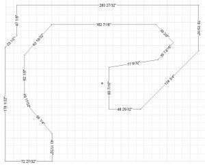
This raises more questions. The NMRA standard minimum between tracks (IIRC) is 2 & 1/16". My peco total width including ties is 1 & 5/16". So, the total of two tracks side by side is 3 & 3/8". Four of them is 7 & 3/4". That would leave approximately 16" for more track, so I could seemingly put 8 more tracks in there (this would be with no room to spare).

So, are you saying I need 3" between centers to run cars? I mean, we are talking 28-30" radius here... are we saying you can not run any cars with parallel tracks in a 29" radius curve? (I am literally asking, not arguing) I am not entirely sure what you mean by "3" on concentric circles".

Keep in mind, I only have two engines that are longer than a 50' car (albeit one of them is the longest you can get). I do not need to run it all the time. Maybe only by itself.

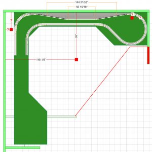
To answer your other question, I might be able to widen the yard area to 30", but it would have to wait as I would need to order more lumber for that.

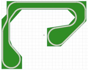
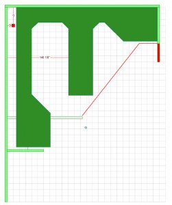
The more I think about this, the more I think your suggestion of deleting the top left blob may make sense. I could add on to the length on the right before it gets to the blob and also make the top yard deeper (to 30 as you say) by using the lumber that was going into the top left blob. This may also cure the 30" min radius problem. What do you think of that idea? I would loose a city, but I could make the town on the right blob larger.

Will do BUT allowing the 24"-25" for the yard area isn't going to leave much room for a yard after the two sets of double track main line running through the area.

You mentioned not want grades because of the extra work.

There is a similar issue here. To run anything you can think of (with the exception of the Schnabel cars) needs 3" on concentric circles.

You can take this down to 2" on parallel straights but it doesn't leave much room for signals - if you think you might every want them.

And it involves laying the track in easements as it transitions from the concentric circles on 3" centers to the parallel straights on 2" centers.

If we can find something that makes you have using 3" centers everywhere it will be simpler for you to build.

Any chance we can widen the yard area to 30"

Thanks, Frederick
 
Last edited by a moderator:
Hi number9

You have to be careful with those standards. I don't know where that came up with those values but they don't work in the real model world.

My two radii are 30" and 32-1/2" with easements into parallel tracks on 2" centers. It's tight at times.

And I didn't allow for signals. I installed some recently and began to have doubts about clearances. A little testing revealed that I had to rethink my signal placement.

You certainly can get by with closer spacing, 2-1/2" perhaps but I was trying to play it safe and avoid any issues for you. And you never know what the future may bring in the way of new equipment.

Help me with my memory here - I don't recall suggesting removing that "blob" - when did I do that???

You could avoid the curve connection issue by keeping the mainline out of there - it would make a nice industrial area.

Let me draw something up and see what you think.

Thanks, Frederick
 
Hi number9,

Here is a rudimentary plan that uses 30" and 32-1/2" radii.

I've moved the outlines of the framework a bit.

1. Is the basic size and shape doable?

2. Is the basic idea acceptable?

I still think something like the "blob" would make a good industrial area but I'm just trying to get a basic mainline down.

Thanks, Frederick
 

Attachments

  • number9 v3 dimensions.jpg
    number9 v3 dimensions.jpg
    138.9 KB · Views: 177
  • number9 v3 plan.jpg
    number9 v3 plan.jpg
    188 KB · Views: 170
I misspoke, someone else suggested removing the blob. I just noted that if I did remove it and add to the blob on the right, I could do it with the lumber I had on hand perhaps, instead of ordering new lumber (which I take a huge loss on as I have to have it cut in 1/2 and delivered, so it is twice the price of normal lumber by the time it gets here).

1. I think the basic shape is doable. The blob on the right may end up being more square at the top, but that is just because of the lumber I have on hand.
EDIT: I misspoke, looking more carefully, on the right hand of the layout, exactly 6 feet from the top of the diagram, there is a door. It opens at the top (meaning the hinges are at 6 feet + 32" from the top of the diagram), and this layout will hit the door. The blob on the right would have to move up. I am not sure if that is possible.

2. The basic idea is acceptable. It is pretty painful to see the mainline eat up so much room on the table after playing in SCARM. By my guess, taking a ruler to the monitor, the yard would only support 5 tracks at most in addition to the mainlines. The blobs look like I might be able to support an industry with no real town around it, so it might be an industry blob and a town blob. I might also have to toss the trolley idea, which would be tough explaining to my other half (the one that is approving me taking over 75% of the basement with "toys").

I went into SCARM and used the measuring tool to check the distances between centers. Yup, a lot of the track is nearly 1/2" under 2&1/16, much less 2&1/2" or 3" center to center. Sigh. I suppose I can not have the yard I want after all.

I am having a tough time understanding how people put so much on a layout. I have 24feet across the top and on the left and from the top to the bottom of the lower left blob I could take it to 24feet if I really pushed it. However, when you put the track down as your software shows, and I think about placing an industry in the lower blob and a trolly circle in the top right blob (which I think is not possible now), it leaves little room for anything else. If five more tracks consume the entire space at the top, that is not going to be enough yard for me. I kind of wish people who had these awesome yards with eight tracks in it would tell us upfront that it is 5 feet deep and 40 feet wide.

You talked about easements, but my eyes don't really see any on this layout. Are we just talking prototypical, or are you incorporating them into this layout?

EDIT: The more I look at the layout the more I think I need to change my ideas of what I want, or get out of this. I think if I ease my restraint on the 30" min (although it looks good in videos) and sell my two large engines, I could be ok with smaller radius curves, like 28". The main problem I see after that is the distance between tracks. I would like a large yard and I don't really want to give that up. I will have to figure out how much room I need. Question, is it not true that in a yard I can put the tracks closer together? All of my rolling stock is 40' and 50' cars. Why can I not go NMRA standard minimum there? That would help a little, I think.

Thanks.

Hi number9,

Here is a rudimentary plan that uses 30" and 32-1/2" radii.

I've moved the outlines of the framework a bit.

1. Is the basic size and shape doable?

2. Is the basic idea acceptable?

I still think something like the "blob" would make a good industrial area but I'm just trying to get a basic mainline down.

Thanks, Frederick
 
Last edited by a moderator:
Hi number9,

Don't give up yet.

How about I start from scratch and show you some of my ideas - keeping in mind the things you have said you want?

Layout design, for most of us, is a set of compromises - it took me a long time to come to terms with the limits I faced - and the things I just had to forgo.

Here is what I came up which gave me most of the operating elements I wanted at the expense of scenery - no towns, etc.

An example of a another compromise I had to make, accepting the complexity of two layers to get a large staging yard. Fortunately I found a fellow that makes custom helix kits and that took a lot care of perhaps the hardest part.

But I did get a decent mainline run, a 8 track passenger yard, a 5 track freight classification yard, a full turntable and engine facility plus 10 small industries.

It's in space 13' by 21'.

The construction photos are from early on.

You've got much more space then that - you can do a lot.

I'll be glad to give it a go.
 

Attachments

  • Layout 3PI Rendering.jpg
    Layout 3PI Rendering.jpg
    106.6 KB · Views: 169
  • TT Area 1.jpg
    TT Area 1.jpg
    202.9 KB · Views: 173
  • Overall 07.jpg
    Overall 07.jpg
    203.7 KB · Views: 180
you could shorten the shelf at the top, have those two tracks closer together. that would move the right blob up and out of the way of the door. you could also extend it more toward the left blob, looks like you have more than needed space to walk into the layout center.
 
Well, I have been looking over the layout since my last post. I took the mainline out of the top left blob in SCARM. I think I like this better, as it will give me more room for a town/scenery, etc. I could even take the industrial spur out and place a trolly in there. Since I shortened the blob wood-wise, this means I will have more lumber (as the measurements here make it so I don't have to cut ply to make it fit).

I also fixed the bottom mainline, which was far too close. I also moved it to avoid the pipe in the floor. There are a few curves in here which approach 27.5" radius, so that is a compromise. Also, the yard will probably have to have a few lines removed (although I did think that you could stack Peco #5 turnouts and go from there without adding track to make them farther apart in a yard, am I wrong?) As it stands, I don't have any real issues with this layout (although I will have to remove some yard). Does this seem OK? I know the turns are not 30", but that is something I might have to live with. I can always sell the Centennial and the AC6000 and just run my short engines. I will admit there is nothing in me that makes me want a passenger train, and we do not like long cars (car carriers, long flat cars, etc).

So here is my current non-perfect SCARM shot:

baseboard3i-test.jpg
 
That is pretty impressive. When I look at your yard, I think the tracks are pretty close together in the yard. I think in the yard the rules are less stringent than they are on the mainline?

I have been looking at the wood pile today, and what I have down in the last diagram (if you ignore the track) is about what I can do with the wood that I have. I might be able to get some more wood, but the cost is very high for me to get it. I could rearrange my wood to make some other baseboard, but I will admit I have pre cut sheets already (four 4'x4' and twelve 2'x8' sheets). I was for the most part happy with the layout I had, until I realized that I need to have a ton of space in between the tracks and curves. Now I do not have so much room for towns. I know the model is a compromise, I would just like to have a fair amount of towns and scenery and more track, but I have to make the family happy too by having enough towns and scenery to let them have a hobby building that part. I think moving the mainline out of the left blob makes more room for a town. I might even only put one industrial spur there instead of the three that I show.

However, if you think you have a good solution in mind and like playing with it, I am open to new ideas.

Thank you.

Hi number9,

How about I start from scratch and show you some of my ideas - keeping in mind the things you have said you want?

Here is what I came up which gave me most of the operating elements I wanted at the expense of scenery - no towns, etc.

An example of a another compromise I had to make, accepting the complexity of two layers to get a large staging yard. Fortunately I found a fellow that makes custom helix kits and that took a lot care of perhaps the hardest part.

But I did get a decent mainline run, a 8 track passenger yard, a 5 track freight classification yard, a full turntable and engine facility plus 10 small industries.

It's in space 13' by 21'.

The construction photos are from early on.

You've got much more space then that - you can do a lot.

I'll be glad to give it a go.
 
Problem

I have just discovered I have a real problem with the layout. I am cleaning up in the basement, and also figuring out how many cuts to make to build the base board. I noted that the door that I am working around is exactly 72" from the top of the diagram on the right. That is the actual edge of the door, not the frame. It opens into the basement, and so this creates a larger problem. I am not sure how my layout got pushed down, but it would need to go up a fair amount on the right and the angle at which the layout comes into the basement would need to be higher. I have attached the current layout and circled what I am talking about on the right. This would need to come up perhaps a foot in order to maintain the same angle and clear the door. I will see if this will work in SCARM, but I am skeptical I can hang on to my "large" radius and do this.

baseboard3i-test-problemcircle.jpg

I wonder if this will work. The mainline coming from the bottom of the yard on the right is under 30" radius already. I can start this turn earlier, and maybe start the top turn earlier also and then clear the door... Ugh. Redoing a load of track in SCARM is not its strong suite. Anyone see an easier way to get around that problem area? Thanks.
 
The current plan from SCARM has some serious issues. I haven't been able to determine how to get SCARM to report on the radius of flex track curves but you got some mainline curves that looks like 15" or 18" radius.

And you've got some "S" curve situations (example: a left hand curve transitioning directly to a right hand curve) that are to be avoid. You need typically 24" of straight track between curves like that.


Why is wood in your area so expensive?


I'll be giving this plan some more thought.

I would not make any major decisions based on that SCARM plan until you can find a way to verify the radius of the suspect curves.

Thanks, Frederick
 
The wood is so high as I have no way to cut sheets here, and I have no truck. It's really painful as I used to have a full woodworking shop and a lumber yard that delivered for free. Now its $60 to deliver and more to cut.

I can go through and figure out the radius. I have to look at the door problem too.

The issue of "S" curves, I did not think about that one. I suppose on the right blob, I could extend it out and that would fix the "S" curve, that too would require more wood. I think right now it is not such a big deal, I just figured out that I do not have enough 1x4s for the support structure and legs.

Thanks.

The current plan from SCARM has some serious issues. I haven't been able to determine how to get SCARM to report on the radius of flex track curves but you got some mainline curves that looks like 15" or 18" radius.

And you've got some "S" curve situations (example: a left hand curve transitioning directly to a right hand curve) that are to be avoid. You need typically 24" of straight track between curves like that.


Why is wood in your area so expensive?


I'll be giving this plan some more thought.

I would not make any major decisions based on that SCARM plan until you can find a way to verify the radius of the suspect curves.

Thanks, Frederick
 
Here is my quick attempt at fixing this, but the middle blob would have a support pole going from floor to ceiling in the middle of it. Ugh.

baseboard3j-test.jpg

I had to remove the left blob for this. I don't really like this layout, I don't know why.
 
You need to really have a good feeling about whatever plan you end up with. While I had to make some compromises on my plan I nonetheless felt good about the design and that it represented a best effort solution.
 
After thinking about this some more, I will spend some time this evening looking at making the plan into a large "L" with two bobs on the ends for the loops. The yard can go in the middle (even though it will go through a curve). This should yield two towns, a yard and if the top right loop is moved a little away from the right hand wall it will avoid the door altogether. The two ends can then have 30" min radius (even with two mainlines) and also the middle turn in the "L" can also be 30". This should be possible with the lumber on hand, and the straight runs can be extended to be 30"-32" wide or so instead of 24" for more track in the yard.

You need to really have a good feeling about whatever plan you end up with. While I had to make some compromises on my plan I nonetheless felt good about the design and that it represented a best effort solution.
 
Hi number9

How about something like this?

Put the yard down the middle - it's not a through yard any more but you have lots of space that doesn't interfere with the mainline routing.

Thanks, Frederick
 

Attachments

  • number9 idea #2.jpg
    number9 idea #2.jpg
    110.3 KB · Views: 177
In another thread (or perhaps the beginning of this one?) I suggested nearly that setup, and the forum gave many reasons not to do it. Then I proposed the triangle layout, and again, there were many reasons given not to do it.

The peninsula down the middle yields a much shorter yard than one on the left and top walls, particularly after you account for having to turn into the peninsula. One of the main goals is to maximize the length of the yard.

You know, in all actuality, if you just took your diagram and removed the peninsula, that is what I was thinking of when I talked about a large "L". :)

Thanks.

Hi number9

How about something like this?

Put the yard down the middle - it's not a through yard any more but you have lots of space that doesn't interfere with the mainline routing.

Thanks, Frederick
 
Last edited by a moderator:
Hi number9.

Here is what you can get in the way of yards along the back.

- Radius 30" and 30-1/2"
- Parallel track spacing 2" - easements used to transition from 2-1/2" spacing on curves
- Depth of straight sections of table - 30"

You can see the dimensions for the longest and shortest track. You could add another track or two but obviously each gets shorter.

When it comes to yard do you need long tracks or just a lot of storage? The peninsula approach would yield a lot of tracks but not long ones.


Also, can you give me the dimensions of the locations of the other two posts - they are marked on the plan with question marks.


Thanks, Frederick
 

Attachments

  • number9 idea #3 render.jpg
    number9 idea #3 render.jpg
    64.1 KB · Views: 169
  • number9 idea #3.jpg
    number9 idea #3.jpg
    155.6 KB · Views: 167
at the bottom of the layout make a turn and bring the bench work back up to the pole in the center of the room.
you can put the yard in the upper left corner of the layout. Have one ladder on the top wall and the other ladder on the left side of the room.

HTH
Steve


Back
Top