Need help removing steam locomotive shell


Can someone direct me towards the correct way to remove the top of the boiler on an OMI FEF-1 4-8-4 HO scale. I don't want to scratch or damage anything but it is REALLY frustrating me! LOL
Thanks,
Seann
 
OOHH, and WTH is the on/off switch under the cab? On a brass model? BTW if you haven't figured it out, it's my first brass loco.... hehe
 
I know how you feel buddy. I remember my first "golden bank", it was a S.P. 0-6-0 Balboa I think. Started a habit I spent over fifteen years feeding. Good luck with that project and enjoy your OMI Northern.
 
Seann,

There should be a screw holding the front truck in place. Remove this and set the truck aside. Located between the cylinders, there should be another screw. This holds the front of the boiler in place, remove it.

At the very back end of the loco, there will be 2 screws located either, at the very end of the loco, down low, or they will be located underneath the cab, generally in the corners. Remove these 2 screws and now, the loco will come apart.

That's the nice thing about brass steamers, they're actually very easy to get into.
 
Last edited by a moderator:
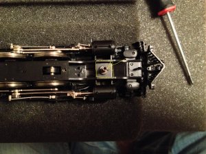
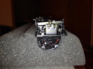
Hey, thanks for the info so far! OK, here is where I have been for almost 2 days now. In the first pic I removed the lead truck and then the long screw I have outlined and an arrow pointing to. In the next pic I removed the 2 rear screws that are outlined w/ arrows pointing to. Also not pictured but on the bottom of the cab were 2 screws I removed and the cab came off. There are no other screw heads visible either on the top or the bottom of the loco. The front of the boiler is able to move about an 1/8" up and down independently of the drivers but the rear still seems to be held firmly by something. Also, it appears that the whole boiler is trying to come off not just the top half.

IMG_3189 yellow box.jpg

IMG_3192 yellow box.jpg
 
Just a thought, is it possible that I need to remove the drivers before the shell will slide off. The only problem with that logic I can think of is that the motor will still be in the boiler which is now a cylinder without the drivers...
 
Just a thought, is it possible that I need to remove the drivers before the shell will slide off. The only problem with that logic I can think of is that the motor will still be in the boiler which is now a cylinder without the drivers...

NO!

Take those three screws completely out. And after they are out, you should be able to remove the boiler from the chassis. Make sure that there are no handrails or other piping, preventing you from doing this. On more modern locomotives from importers like OMI, Division Point, PSC, the quest for detail is now so great that you now have to look for things like that. The wider screw that the long screw goes into, don't remove as it holds the cylinders onto the chassis.

Alan, Espeefan, may have a suggestion that I don't know about. I'm surprised that this thread hasn't caught his eye.
 
It did catch my eye Carey, I just didn't have anything to add at this point. You are right where I would be at this time. If those two screws are out and no other screws are visible the boiler should come off. Like Carey says, there may be piping or detailing interfering with removal. Sometimes the motor is a very tight fit as well and you have to move the boiler back and forth to work the motor out. I have seen almost interference fits between the motor and the slot in the boiler in some models. Note: The the boiler will come off as a complete assembly, not in halves, leaving the chassis as a separate assembly.

As Carey says, do not remove drivers. I would leave the running gear alone unless your mechanical skills are very good. There is no reason to take it apart. There is already a cam in place, so if it works, don't fix it! If the chassis is held firmly at the rear with all visible screws out, you must have missed something.

I just took a pair of Overland 4-8-4's into the shop for sound installs. If you can wait until this evening I'll look at one of them. The method of assembly should be similar.
 
I got it thanks!!! I can't tell you how much I appreciate all the help so far!!! The front grabs were a small problem (not used to the wire coming out of the mounts. On plastic the mounts come off.) The biggest issue was the motor being so tight. I was using delicate hands and was afraid of it.
My next problem- I have a can of worms I think. There is a slight bind in the drive somewhere, and the rear driver is way, way to high. I think I know the reason it was sold. On my bench the lowest I can get it to run is at 2.2v. Anything lower and it has to much friction to turn the drivers. The reading I have done on this tells me I should be able to get full revolutions at about 1v with the cannon motor/gear box in this loco. Does 1v sound about right to you guys?
As far as the rear driver, how do I fix this? How do I know what is level on the frame to determine if it is actually the rear driver being to high or if it's the 2 front divers pushing down to much. I double checked the bottom plate to make sure it was compressing the bushings all the way. is the frame milled out of spec or is it something I'm not noticing? I will add a pic as soon as the wife gets home with her I-phone.

Thanks,
Seann
 
Chances are the "too high" driver is being caused by a badly compressed spring. Each driver/axle assembly is supported by springs under the bearings.You can check this y pulling down on the driver in question. If it stays down after this, the compression may be relieved. If there is a binding in the mechanism, it could be from this.

Definitely need to see the pictures.
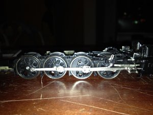

I was thinking I needed to address the driver height issue's before I messed with the binding issue. I'm glad I was in the ballpark. I am taking pictures now. Thanks again!
 
OK so, it's kinda hard to see but it the rear driver is up a little more than the thickness of a business card. One thing I want to try is flipping the bottom plate. I noticed when I got the loco apart the builder plate was on the inside. All the pictures I have seen of brass has it on the bottom so you can see it when you flip it over.

chassis.jpg
 
Since this is your first brassie, be careful that you don't allow the drivers to come out of the slots. From what it looks like to me, it appears that the spring that should be there, is gone, or very badly compressed.

If while you do have the gearplate off, if you can lift that last driver/axle assembly enough to see if there is a spring underneath the bearing. If there isn't one, it means that you'll have to replace it. Not hard at all, you just have to be careful.

We'll get into replacing the spring if that is what the problem is.
 
I would agree with Carey so far, and add the following: Flipping the cover plate won't make any difference. It has never mattered on any of the hundreds of models I have been into. Since that last driver is up higher then the rest I am almost certain there is a compressed spring or the spring is off of its mounting peg and causing a bind in the driver's up and down travel. Can you pull it down into place?

Question: when you get the cover plave off, look and see if you have individual spring pairs for each driver or a long piece of spring wire on each side. Both configurations are possible depending on when the model was made. Which do you have?

Second question: Do you have the little hex driver for the driver screws? Third question: Is the original parts bag with spare screws springs and such present?

I don't know how much experience you have but if you are new at this proceed slowly!
 
Ok, I was able to dig a little more into it. First, like you said Espee, the cover didn't make a difference. (Question #1) Each driver has a spring for each bushing. I pulled the first 2 divers up out and removed the springs. They are all the same length. So I checked the frame to see if something could be wore down or off and nothing is showing up. I put the drivers back in and checked to see if the springs were seated right. They were. Installed the bottom plate and they are high still. Next, I removed the plate and checked the reveal of the bushings sticking out of the frame. The rear bushings stuck up about the same as all the other ones. So, bottom plate back on and another check, still high. Just for giggles I put a straight edge on the top of the frame where I could get it and it looks like the straight edge is touching on the ends. Like the frame is in the shape of a smile...
(Question #2) I have a set of jewelers nut drivers that I use on my plastic steamers but they won't fit the brass. The head of the hex is sunk in a little bit and it is also very shallow compared to the ones used on plastic. I will have to grind one of the drivers down to a thinner wall to see if it will fit.
Another question. Looking at this thing it looks like the crank is soldered to the pin. Is this normal? Do I need to de-solder it to remove the linkage?

Thanks,
Seann
 
It's good that the drivers are individually sprung. All of the Overland FEF-3's were made by Ajin, and they were/are good builders. I really don't like the "frame looks like a smile" thing though! That's a problem. The real test here is to remove the drivers and check the bottom of the frame with that straight edge. Make sure it's a good one, machinist quality. I believe that is where your problem lies. The frames on the newer models are not as beefy as they were on the older PFM and Westside models. If it is bent, and I think it is, that's why that driver is sitting high. Did the previous owner drop it? Did someone have it apart and bend the frame? Was it a factory defect? Hard to tell.

I checked one of the Overlands here, and the eccentrics are soldered to the crank pins. You can unsolder it to remove it or just unthread the assembly. Having done both I think unsoldering is easier. There should have been a wrench with the model. Look under the foam It may look like a piece of black tubing


Back
Top