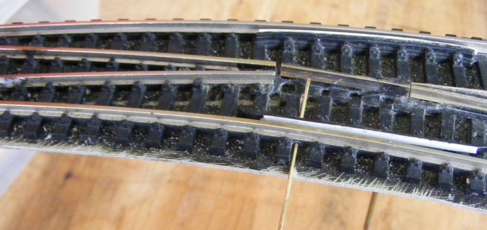
Gap-less Turnouts, reducing wheel dips in turnouts


beiland

Well-Known Member
I'm returning to this idea that I suggested back a few weeks ago,...a swinging frog I think it would be called?


railandsail wrote:
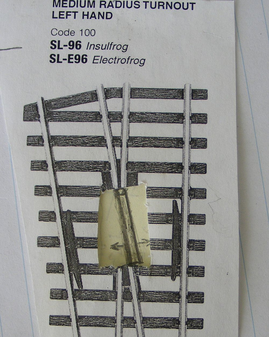
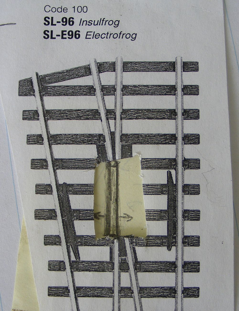
Okay this is just a really rough sketch at the moment, but perhaps it conveys the thought,...my swinging frog.

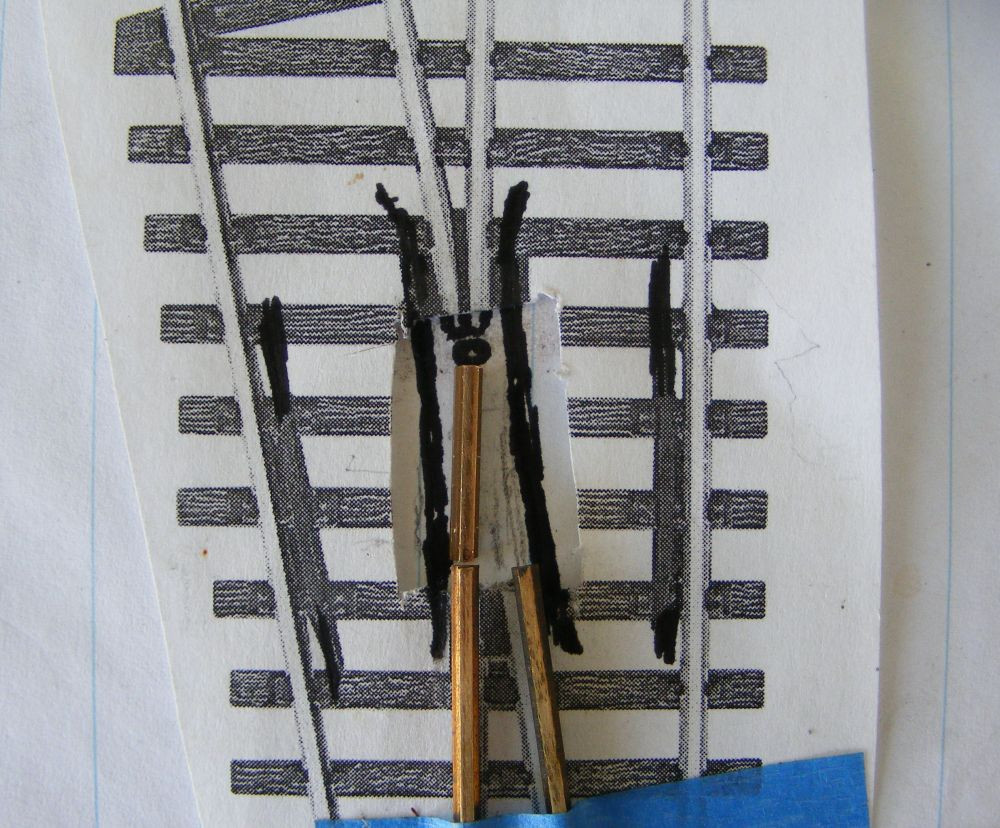
I cut out the location of the stock frog area on a Peco medium radius turnout, and inserted a plain sheet of yellow post-it note behind it
The new 'frog' would be that solid piece of metal that wold rotate around the 'pin' at the one end (circular pin shown) . It would swing from one side to the other and its two sides would line up the inner faces of the tracks in either of the 2 directions. It would allow the wheels of the rolling stock to roll over either of its solid metal edges,...thus a true GapLess turnout.
DSCF8927.jpgDSCF8928.jpgDSCF8929.jpg


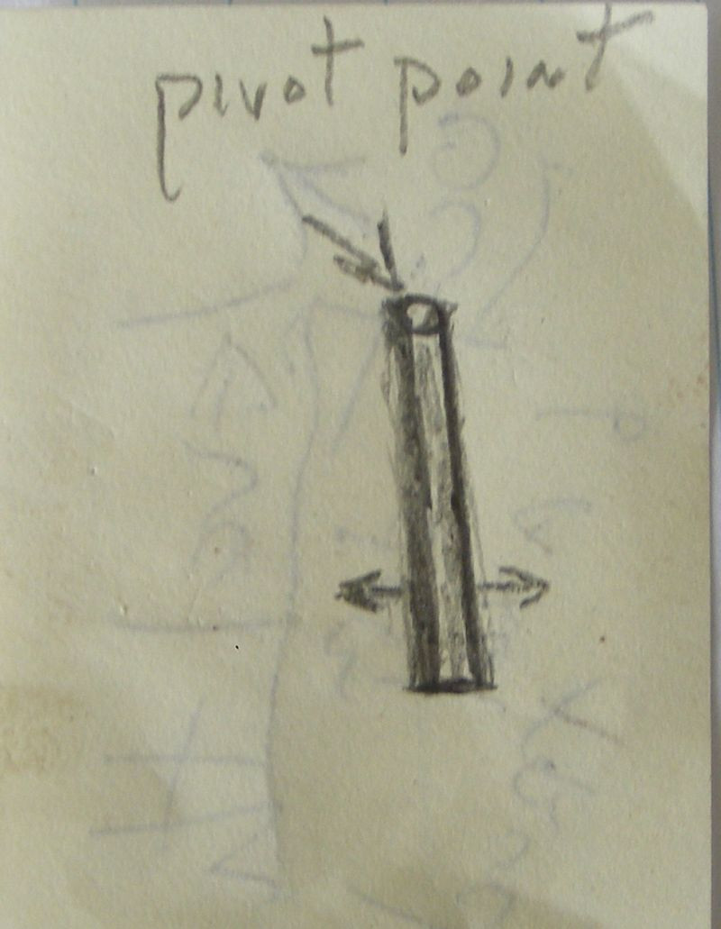
I think I described this incorrectly in my original posting, "The new 'frog' would be that solid piece of metal that wold rotate around the 'pin' at the one end (circular pin shown)". It would NOT rotate around that pin, but rather be a part of the pin,....

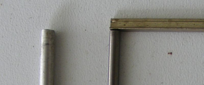
My frog would be all one piece,...the short piece of rail attached permanently to a circular pin at one end,...something akin to this...
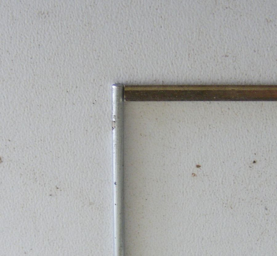
DSCF8949.jpg

That vertical pin must be a true 90 degrees to the rail piece. It accomplishes several things;
1) it assures the frog rail swings in an exact level manner
2) it keeps that frog rail from twisting over
3) it could be longer, stretching down thru the deck work, thus even more stability,... and maybe be rotated ever so slightly to rotate the frog rail

Here is the general configuration,..
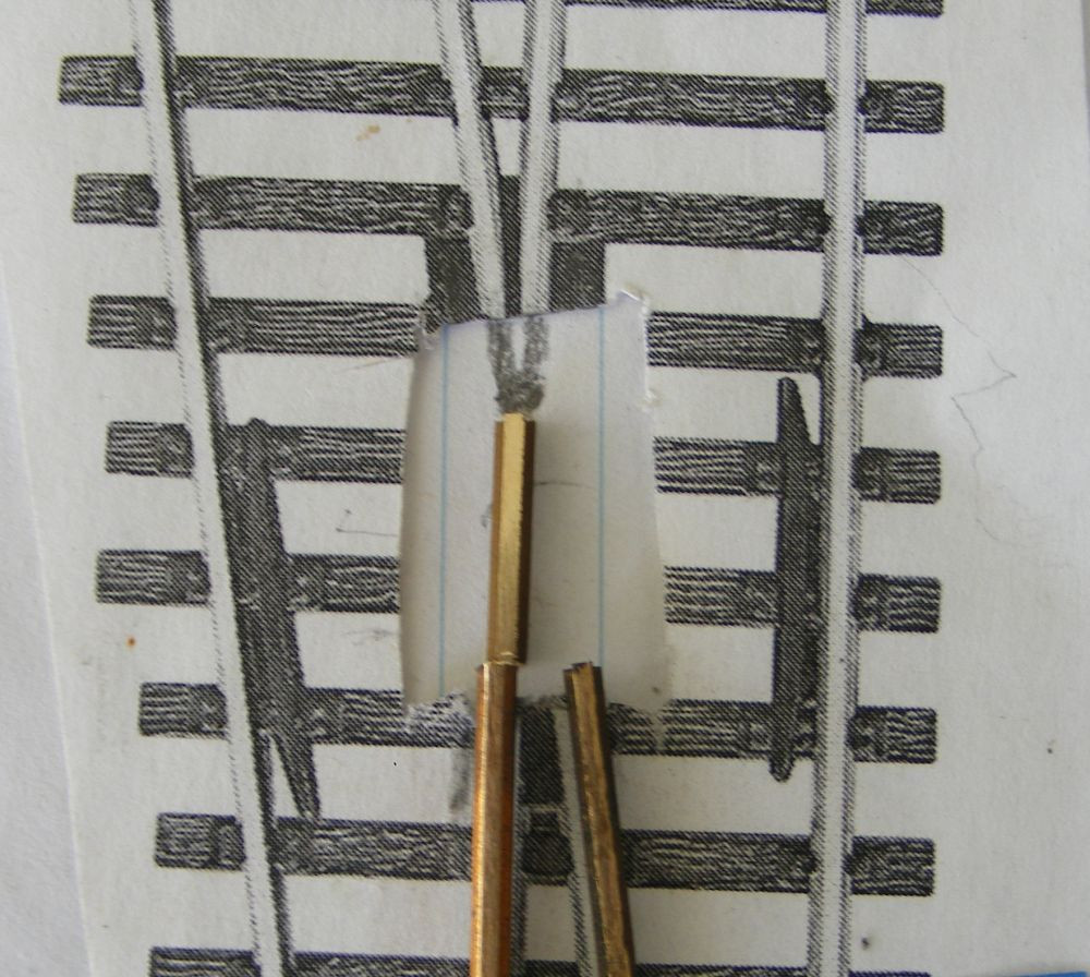
DSCF8952.jpg

DSCF8951.jpg

Wing/Guard rails could be added around that swing frog, and might even be applied in such a manner to limit the swing of that frog piece to either side.

EDITIED: BTW the circular pin is NOT attached to those rails exiting the frog area. it is only attached to the short swing frog rail.
 
I'm returning to this idea that I suggested back a few weeks ago,...a swinging frog I think it would be called?


railandsail wrote:
Okay this is just a really rough sketch at the moment, but perhaps it conveys the thought,...my swinging frog.

I cut out the location of the stock frog area on a Peco medium radius turnout, and inserted a plain sheet of yellow post-it note behind it
The new 'frog' would be that solid piece of metal that wold rotate around the 'pin' at the one end (circular pin shown) . It would swing from one side to the other and its two sides would line up the inner faces of the tracks in either of the 2 directions. It would allow the wheels of the rolling stock to roll over either of its solid metal edges,...thus a true GapLess turnout.


DSCF8927.jpgDSCF8928.jpgDSCF8929.jpg


I think I described this incorrectly in my original posting, "The new 'frog' would be that solid piece of metal that wold rotate around the 'pin' at the one end (circular pin shown)". It would NOT rotate around that pin, but rather be a part of the pin,....

My frog would be all one piece,...the short piece of rail attached permanently to a circular pin at one end,...something akin to this...
DSCF8949.jpg

That vertical pin must be a true 90 degrees to the rail piece. It accomplishes several things;
1) it assures the frog rail swings in an exact level manner
2) it keeps that frog rail from twisting over
3) it could be longer, stretching down thru the deck work, thus even more stability,... and maybe be rotated ever so slightly to rotate the frog rail

Here is the general configuration,..
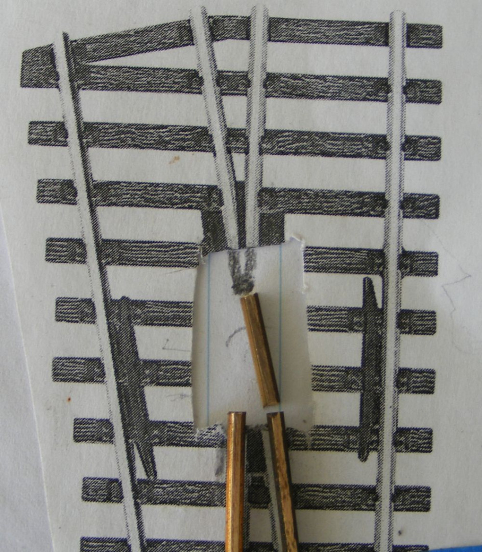
DSCF8952.jpg

DSCF8951.jpg

Wing/Guard rails could be added around that swing frog, and might even be applied in such a manner to limit the swing of that frog piece to either side.

EDITIED: BTW the circular pin is NOT attached to those rails exiting the frog area. it is only attached to the short swing frog rail.
Looks very interesting, and an improvement on what is around, but my concern is that where the track that swings between the two directions would also have to be able to switch polarity.
 
Good observation there. I think it would have to be treated the same as an electrifrog Peco,...you would have to add insulators to the 2 tracks exiting the frog area,...and the frog track itself would preferable need to be powered up like a live frog in DCC systems
 
Kind of a neat concept. If I'm following your thinking here, you could glue small strips to make stops. you would have to have that rail be perfectly aligned, or it will cause issues.

I'm assuming this will be a manual throw?
 
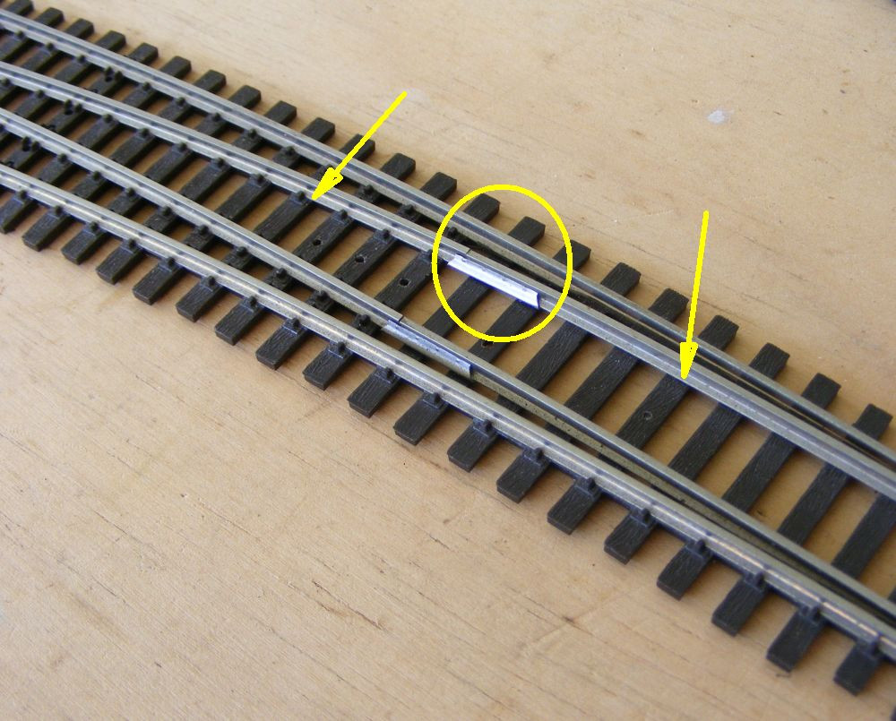
Some 'fake wing rails' could be added to provide a positive stop for the swinging frog piece.
DSCF8960.jpg

Those fake wing rails could tend to make the turnout look more prototypical (from a distance),...for those modelers concerned with those details.

I need to think up a simple manner to connect the movement of that frog piece with the more conventional throwbar that operates the point rails,....so there are not 2 separate motors nor manual operations needed to throw the turnout. I don't see a need for great precision ? That swinging frog piece swings between 2 positive stops on either side,...the stops provided by those fake wing rails. And just like most other commercial turnouts, the point rail's throw bar moves the rails from one side to the other. No precision required?

Any ideas folks?
 
I have a LOT of learning to do to learn how to operate my trains with DCC, so I'm trying to keep this turnout design idea at a distance,....BUT it keeps re-entering my mind.
 
My Needs/Desires, VERSES, the Challenge of Gapless Frogs

Lets see if I can clarify my reasonings here;
1) I am NOT looking for gapless turnouts to accommodate various freight car wheel sizes. I would be better off seeking wheels of a more proper size to fit my commercial Peco turnouts.

2) I am looking for gapless turnouts for my locos, quite a few of which have some 'oversize wheels'. Some of these locos are difficult, or impossible, to find 'modern size wheels for.

3) I don't need for all of my turnouts to be gapless, as I have managed to shim some of the stock commercial turnouts to work,..even with their dipping characteristics . And not all track configurations need gapless turnouts.

4) Upon my shimming and modifying operations, I became intrigued with the idea of a gapless turnout,...and that lead me to the old Tru-Scale concept .
It would be a challenge to modernize that old concept, and concurrently make it easy for a neophyte modeler to build his own, OR have a easy kit to build, or have a cheaper turnout that does not involve high cost of investment tooling, nor high labor cost to build.

5) And then after exploring a fair amount of the old Tru-Scale history, I reverted back to this swing frog idea, that should be even easier to self build, or have some sort of kit.
 
A primary reason I would like to have turnouts that would accept different size wheels,..

I have a whole host of these Mehano C&O Mountain locos that have larger flange wheels

So am I just expected to sell them,... or throw them out as they likely will not run thru the latest 'dip-free' turnouts??
[age%28274%29]

[age%28277%29]

[age%28269%29]

In addition to those I have a nice oriental express set thats lead by a Lima locomotive with larger flange wheels.

I also have a TGV set from France with larger flange wheels.

I think i still have a few of those older Rivarossi steamers, nicely weathered and with good motors, larger flange wheels.

Several nice Roco steamers from Europe (that outpull many of my American steamers),...and have larger flange wheels.

ETC,...and more I can't think of at the moment.

Then on to more modern engines that have trouble with the larger gaps of commercial turnouts,....like the AC6000 diesels from Broadway, and some of the Genesis engines, both 6 and 4 axles.

This is what has lead me to this desire to see if a NO-GAP turnout could be developed in this modern day,...and particularly one that would be easier to build than the Fast Track ones.
 
My idea was to generate ideas and suggestions for a way to make a no gaps turnout in HO, possibly code 83, for 110 wheels/or even 80. So if this is feasible, that's what could be done. MR's are ingenious in making "things work".
It may be a limited market, but for those MR's that run long passenger trains at fairly high speeds, would like a no gaps #6 or #8 turnout for the main line. ??
And just because the proto only does that for #20 turnouts, don't mean modelers can't use it for #6 or 8.
Morgan
 
n addition to those I have a nice oriental express set thats lead by a Lima locomotive with larger flange wheels.

I also have a TGV set from France with larger flange wheels.

I think i still have a few of those older Rivarossi steamers, nicely weathered and with good motors, larger flange wheels.

Several nice Roco steamers from Europe (that outpull many of my American steamers),...and have larger flange wheels.

ETC,...and more I can't think of at the moment.
Maybe I missed your post somewhere, what track are you using, code 83 ?
 
I need to think up a simple manner to connect the movement of that frog piece with the more conventional throwbar that operates the point rails,....so there are not 2 separate motors nor manual operations needed to throw the turnout. I don't see a need for great precision ? That swinging frog piece swings between 2 positive stops on either side,...the stops provided by those fake wing rails. And just like most other commercial turnouts, the point rail's throw bar moves the rails from one side to the other. No precision required?

Any ideas folks?

[mcnk2s] [mtub2s]

It's called "wire in tube". In common use on UK layouts since the 1950's. Although nowadays, ptfe tube has replaced the copper tube shown.

A simple crank as above can mechanically split a throw to two destinations and/or optionally reverse one. Hence my posting of the little crank kit earlier.

Andy

OF COURSE !!, what an idiot I am,..
.....and I have used some of these wire within a plastic tube turnout controls on my current layout, but they were all direct in-line versions, so I guess that's why I didn't think of it. I am such an idiot at times !
 
Some updated ideas for this swing frog concept

I had previously written,...
Quote:
My frog would be all one piece,...the short piece of rail attached permanently to a circular pin at one end,...something akin to this...
DSCF8949.jpg

That vertical pin must be a true 90 degrees to the rail piece. It accomplishes several things;
1) it assures the frog rail swings in an exact level manner
2) it keeps that frog rail from twisting over
3) it could be longer, stretching down thru the deck work, more stability and maybe operate its small rotation?

Here is the general configuration,..
DSCF8952.jpg

DSCF8951.jpg


With that former iteration the diameter of the vertical pin was limited to the width of the head face of the rail, which can be pretty small.
How about we change this configuration so we have a more hefy size pin, and we don't bring it up flush with the top face of the frog rail. Instead we attach the pin/shaft to the bottom flange of the swing frog rail,...like these 2 possibilities
DSCF8971.jpg

1) larger attachment surface area
2) easier joint to make (maybe even adhesive)
3) better/stronger shaft size

This new turnout as a whole is now easier to build,...less filing/grinding/fitting of adjacent rails, and less soldering.
one would still have to create the V-joint of the 2 rails leaving the frog area, but these 2 would not be the very pointy items they are today. They would end in a 'bluntness',..the width of running surface of the rail being used to build the turnout.

There would still be the grinding/filing of the 2 point rails where they met the mail rails. There likely would not be any gross pivot points between the point rails and the closure rails, but rather something like Shinohara used,..
DSCF8962.jpg
or maybe no joints at all, just long bent closure rails?

This 'gapless turnout' is sounding more doable, and easier to build.
Great, so where do we send our orders to ??:D
 
Control Linkage for my Swinging Frog

In the past there have been a number of folks asking about controls to operate this gap-less turnout, and some of those folks suggesting it is going to be very difficult.

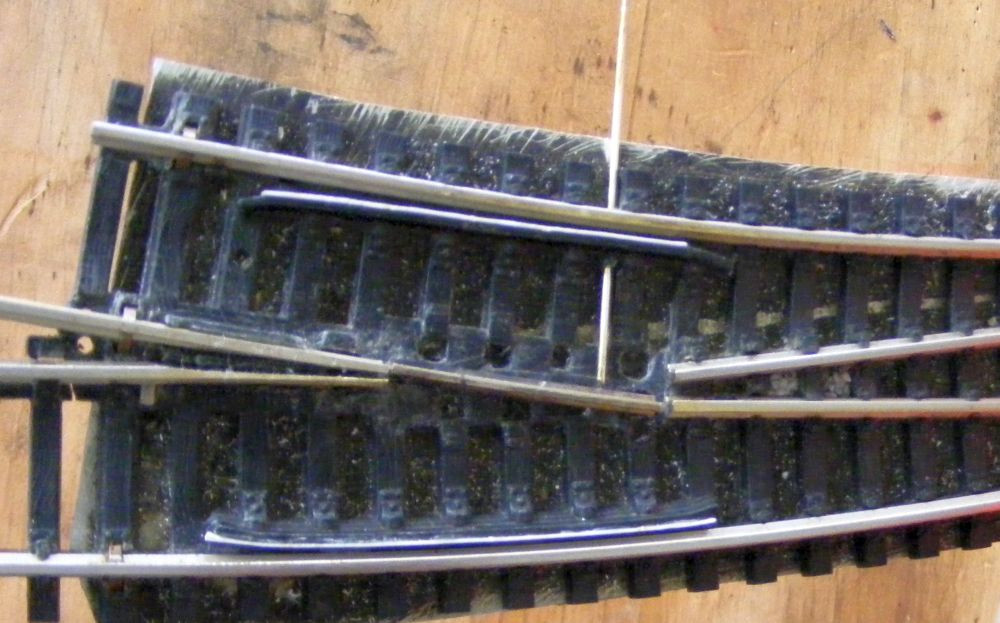
Here is my latest thoughts on controlling that swinging frog,...a simple one piece length of music wire attached to the swinging end of that track piece. It could be easily camouflaged along side one of the ties. (and the rod shown is oversized to what would be required)
DSCF9117.jpgDSCF9119.jpg
 
Swinging Frog by
Fleischmann EXPRESS turnouts

[%252C%2520ps]

That doesn't look too bad does it,...unusual / non-prototypical? Looks better than my single swinging track version !

Operation,...(by the way there is a simple way to slow the video down, that I just learned,...and it may be easier to see this video)


PS: Why hasn't some American firm done something like this over the past how many years is it??
 
So no one on this forum has an interest in a gap-less turnout?
Beiland: Gap-less is probably a good idea; although I have had zero problems with ...um... normal turnouts yet! Do note that there are prototypical ones for movable frog wings. If I remember I found one on the BNSF somewhere and think that I took a couple of pix of it. It was into a siding ( or the start of 2 Main tracks ) and looked to be a 'high speed' thing. Route signal going in had two 3 light heads of which the bottom ( diverging ) head would show Green vs Yellow/Lunar.

Later


Back
Top