EMD TR5A


flyboy2610

Loveably weird
It's a chilly, cloudy, windy day today. This kind of weather often makes my right knee act up, so working under the layout on the wiring is not something I want to do today. Maybe tomorrow.
I decided instead to start work on a project I've been meaning to get around to for quite some time: re-motoring an old Athearn TR5A, and adding DCC and sound.
The TR5A was a switch engine produced in 1951 and 1952. The design was based on the SW9, and was used in a cow/calf configuration. A total of 10 A units were built, and 12 B units. Mine is #1870, and I do not have a B unit. I do, however, have a extra shell, so I'm going to be on the hunt for a chassis I can use to kitbash a B unit.
These are the old style Blue Box locomotives with metal side-frames attached to the trucks, and the open frame gray motors. I have heard those motors referred to as "baby elephant" motors! I checked the stall current of the motor, and while I don't recall exactly what it was, it was fairly high, even after a thorough tune up. So if I want to go DCC, which my layout is, a re-motor is in order.
This is what I'm working with:
100_0012.JPG


I have already had a decoder in it once, but it didn't work too well. The headlight has an LED in it, but I never did the back up light. You can see how the shell attaches with horizontal tabs, rather than round nubs as the newer Blue Box locomotives have. The fiddly bits are in the KFC container. Those containers (after you have eaten the contents, of course) come in quite handy for purposes such as this. I have 3 Digitrax N scale sound decoders, and 1 HO Digitrax sound decoder. I haven't decided whether to use any of those, or go with a Soundtraxx Tsunami. I'm leaning towards the Soundtraxx, probably a board style decoder.
The black can motor is what is going in. I bought 10 of those motor on FleaBay several years ago, and never got round to installing any! Gonna have to rectify that oversight. I am also going to get rid of the flywheels. Trying to keep them would cause more problems than it would solve, so they're going bye-bye!
For the driveshaft I am going to use silicone tubing. Pictured is Du-Bro #221 small diameter RC fuel line. Interior diameter is 1/16" (.0625), or very close to 1-1/2mm. The motor shaft is .079, and the worm gear shaft is .092, so the fit should be fine. Before I install the tubing, I'm going to give the shafts a rub with some sand paper to roughen the surface, so the tubing should hold even better.
To get the motor installed anywhere even close to where it needs to be, some modification needs to be done to the frame. As it is, the motor sits much to high, so the frame will have to be milled down. All the milling will have to be done to the front half of the frame.
Here is a pic of the back half of the frame:
100_0013.JPG


As you can see, if I try to mill any of that down, it will seriously weaken the structure of the frame! Can't have that, now, can we?
Here is a pic of the front of the frame. You can see there is much more material to work with on this end:
100_0014.JPG


I don't recall why I installed that screw. I use the old front headlight post as the spot to solder the wire for frame side power.
More to come!
 
Well, I'll be dipped.
It actually worked! And some people say miracles don't happen!
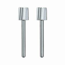
As mentioned in my previous post, some milling of the frame is in order here. Problem: I don't have a milling machine. I do, however, have a couple of Dremel high speed cutters
a drill press, and a 2 axis drill press vise. What could go wrong?
Here's my somewhat dodgy setup, after having done most of one side:
100_0015.JPG


Drill presses are not really designed for side loading the chuck like this. I have the cutter installed as close the chuck as I could get it, and the RPM is 3070. The gibs on the vise aren't the greatest, so I wouldn't try doing high precision work with it, but it did OK for what it needed to do here.
Side view. The frame in the back has been milled, the front still needs to be done.
100_0016.JPG


Both sides done.
100_0018.JPG


Side view.
100_0019.JPG


After test fitting the motor, I found that I still need to mill the wide areas down about 1/8", and even with the narrow area of the milled surface. That will make a nice pocket for the motor to sit in.
But that's not a problem, because now I know how I'll do it! :)
 
I have a couple of 1/8 and 3/16 inch end mills that I use in my drill press. I set the depth of cut on the quill, do all the milling in a downward motion. A two axis drill press vice works well. Setting up the work true and level really helps. You just need to have patience, don't rush anything or things will break. Not as precise as a milling machine but will do the trick for work like on a loco frame.

Flyboy..............Waiting to see your finished project. Thanks for posting.
 
Thanks, John! The cutters I have say specifically to use the sides, not the tip, so that's why I went that way. It took some time, but turned out well.
I think I still need to make a couple more passes on each side. The motor fits, but it's kind of snug. I'd like just a bit more clearance on the sides.
I plan to use DAP Alex Plus siliconized latex caulk to mount the motor. It dries clear and holds well.
I need to pick up some cutters like you have.
 
In regards to "percent of grade".
Most may know this but this info is for those that do not.
Lets start with a 2% slope. Correctly shown as 2.00%. Now, move the decimal point to the left 2 digits. Now we have 0.02000.
0.0200 is now the tangent of an angle .
Most handheld calculators have Sin Cos Tan functions. Most also have a button to achieve the inverse functions usually referred to as arc-sin, arc-cos and arc-tan.
Back to our 0.02000 number. Enter this number in your calculator do the arc tan function and you should now have 1.1458. This is the angle in decimal form as 1.1458 degrees which equates to 1 degree, 8 minutes and 45 seconds.
This angle may be a bit hard to set up on your layout so lets do something else.
That tangent number, 0.02000 is the tool to use for figuring the slope dimensions on your layout.
Take 0.0200 and multiply by 12 (number of inches in a foot) and we get 0.2400.
12 inches represents the base of a right triangle (horizontal length) times the tangent gives the rise, the 0.2400 number. 0.2400 equates to 3.84 sixteenths of an inch. You can round this up to 1/4 (4/16ths) inch rise in 12 inches of horizontal length. But using this rounded up number will accumulate as you add more 12 inch lengths. So........
For more accuracy lets take an even rise number like 1 inch. To achieve 1 inch rise at 2% slope you need 50 inches of horizontal length.
So now 12 1/2 inches gives us 1/4 inch of rise exactly ; 25 inches gives us 1/2 inch rise ; 37 1/2 inches gives us 3/4 inch rise.
To sum up: 1% slope use .01000 as a tangent
1.5% slope use .01500 as a tangent and so on.

If you have a sloping section on your layout and you want to know the percent of slope (grade) of that section of track, then set up a level, lets say a 3 foot level. Set one end of the level on the high end of the track (roadbed, etc) and while keeping it level, measure the distance between the top of the track (roadbed etc) to the bottom of the level. Lets say you measured 3/8 of an inch.
Now 3/8 of an inch equates to .375 decimal and your 3 foot level converts to 36.00 inches. (we have converted all numbers to decimal inches)
Dividing .375 by 36 will give you 0.0104. That 0.0104 number is the tangent of the angle so move the decimal point 2 digits to the right and now you have 1.04. This is 1.04 % of grade. Not bad.

I hope this helps and is not confusilating to you. It is just trigonometry. o_O🥱
There may be a better way but this is what I use.

Take care....John
 
Hey, y'all!
I haven't abandoned this project.
I soaked the frame in vinegar overnight to de-oil the frame and etch it slightly, then thoroughly cleaned it with isopropyl alcohol. After it had completely dried I gave it two light coats of Rust-Oleum etching primer, waited 30 minutes, and gave it 3 light coats of satin black paint. Came out pretty good, I think. Here's about how the motor will sit in the frame:
100_0022.JPG


Once I actually install it I'll level it up with the worm gear shafts. I don't plan to cut the motor shafts back, as doing so will increase the distance between worm gear and motor, meaning a longer length of silicone tubing between the two. The shorter the tubing, the less chance of it twisting during operation.
Here's a top view:
100_0021.JPG


It's hard to see, but I have put the original motor mounts back into the frame. The motor is sitting on them, and they help position the motor. The motor will be installed with siliconized latex caulk. That stuff holds pretty good, but retains a small amount of flexibility.
Why haven't I already installed the motor? I got to thinking (which is usually dangerous for me to do) and decided that these metal side-frames posed a risk of letting the magic smoke out of the decoder if they contacted the locomotive frame. My LHS owner agrees with that, BTW. I got online and found an Athearn SW7 calf unit, with plastic side-frames, for a decent price. It should be here by next weekend. I plan to swap the trucks between the two, and use a piece of styrene to fabricate a drawbar between them.
For the decoder I bought a Soundtraxx TSU-PNP8 #885813 board style decoder. I really like Soundtraxx decoders. I use them whenever I can. The plan is to put a piece of styrene on to of the motor and mount the decoder to that.
I also bought their #810160 small Current Keeper. I plan to paint the shiny white plastic wrap black, and install it in the cab. For the lights I'm going to use 1.8mm LED's from Evan Designs, which I bought at my LHS. They come pre-wired with resistors.
100_0020.JPG


I suppose I can install the lights while I wait for the calf unit to arrive. I still need to run track power to the relocated double crossover, as well.
 
Well, Athearn's foobie department did it again!
Not being particularly well educated on the differences between the various switchers I did not notice something.
These are not SW9's, which Uncle Pete's DS1870 TR5A is built from. These are SW7's. I have learned that the most obvious difference is the number of louvered doors on the side. SW7's had 6, while the SW9's had 8. These models have 6. :(
While the SW7's were also produced as cow-calf TR unit's, they were designated as TR4's. Uncle Pete never had any TR4's. UP didn't purchase TR units until the SW9's came out, and they were TR5's. They did have SW7's, however.
I haven't decided what to do. Do I renumber the units as SW7's, which UP never ran as TR units, or do I keep the DS 1870 number, which is accurate for an SW9 based TR5, even though these are SW7's? 6 of one , a half dozen of the other, I suppose.
The calf unit came, and I have gone through the trucks, cleaning and re-lubricating them. I also replaced the steel wheels that it had with some new ones from Athearn.
I've decided to use the extra shell that I had for this project. It has the horn, which the painted shell is missing, and this way I can keep the painted shell as a reference for masking purposes.
100_0028.JPG


The TR5 pics which I have been able to find show the truck side-frames being silver colored, so I gave all the side-frame's a quick shot of Rust-Oleum silver (I'm still mad at them for killing off the Testors Model Master line!) For the shells I'm going to use Badger ModelFlex acrylic paint. I haven't used this paint before, but I've read that while it is airbrush ready straight from the bottle it works better if you add a couple drops of flow improver per 10 drops of paint. I have a bottle of Vallejo flow improver, so that's what I plan to use.
100_0029.JPG


Once the side-frames are weathered, they'll look pretty good. The Badger paints are 16-24 UP Armor Yellow, and 16-25 UP Harbor Mist Gray. Badger needs to hire someone that knows how to research and spell properly. It's not "Armor Yellow", it's "Armour Yellow". That's the research part.
The spelling part?
100_0030.JPG


Time to get the shell into the denatured alcohol. I've found that does a good job stripping paint, but it doesn't hurt the plastic.
I need to set up the paint booth and do some practicing with the airbrush, haven't used it in quite some time.
 
I'm not sure what paint the previous owner used on that red shell, but I'm guessing from the looks of it that it was Rust-Oleum rusty metal primer. I've used that in the past, not on plastic models, and it looks just like that. 2 days of soaking in denatured alcohol didn't touch the paint, 2 days of soaking in 91% isopropyl alcohol didn't touch it, but 1-1/2 days of soaking in full strength Purple Power took it off pretty well. Purple Power is pretty strong stuff. It's corrosive, so use caution when working with it. I used chemical resistant rubber gloves

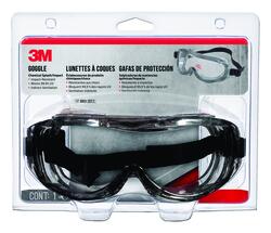
and splash proof googles.

You don't want to take chances with that stuff. But it did a nice job removing the paint.
The little white piece on the calf shell is 1/16" styrene rod. I glued it into the hole in the shell where the bell would be if it were a cow shell. The calf units didn't have a bell. I'll trim it flush before painting.
100_0031.JPG


I'll set up the paint booth tomorrow. For primer I am going to use Testors Model Master white primer. The reason I plan to use white is because I'm going to be painting most of the shell yellow, and yellow doesn't cover darker colors well. So I'm using white primer rather than gray. The factory painted model will serve as the pattern. Doesn't look like a complicated paint scheme.
I'll apply the primer, then the yellow, then the gray. The red stripe will go on last. Once the paint is applied, I'll give the shells a coat of gloss clear, then do the decals. Flat clear will seal the decals, and provide a base for the weathering. I'm going to assemble the models, weather them, flat clear them, then disassemble them and add the wheels. That way the weathering will all tie together.
I'm going to wait until the weathering and reassembly is complete before re-motoring the cow, and adding DCC and lights.
It's going to take a bit of time, but I'm not in a rush.
 
In regards to "percent of grade".
Most may know this but this info is for those that do not.
Lets start with a 2% slope. Correctly shown as 2.00%. Now, move the decimal point to the left 2 digits. Now we have 0.02000.
0.0200 is now the tangent of an angle .
Most handheld calculators have Sin Cos Tan functions. Most also have a button to achieve the inverse functions usually referred to as arc-sin, arc-cos and arc-tan.
Back to our 0.02000 number. Enter this number in your calculator do the arc tan function and you should now have 1.1458. This is the angle in decimal form as 1.1458 degrees which equates to 1 degree, 8 minutes and 45 seconds.
This angle may be a bit hard to set up on your layout so lets do something else.
That tangent number, 0.02000 is the tool to use for figuring the slope dimensions on your layout.
Take 0.0200 and multiply by 12 (number of inches in a foot) and we get 0.2400.
12 inches represents the base of a right triangle (horizontal length) times the tangent gives the rise, the 0.2400 number. 0.2400 equates to 3.84 sixteenths of an inch. You can round this up to 1/4 (4/16ths) inch rise in 12 inches of horizontal length. But using this rounded up number will accumulate as you add more 12 inch lengths. So........
For more accuracy lets take an even rise number like 1 inch. To achieve 1 inch rise at 2% slope you need 50 inches of horizontal length.
So now 12 1/2 inches gives us 1/4 inch of rise exactly ; 25 inches gives us 1/2 inch rise ; 37 1/2 inches gives us 3/4 inch rise.
To sum up: 1% slope use .01000 as a tangent
1.5% slope use .01500 as a tangent and so on.

If you have a sloping section on your layout and you want to know the percent of slope (grade) of that section of track, then set up a level, lets say a 3 foot level. Set one end of the level on the high end of the track (roadbed, etc) and while keeping it level, measure the distance between the top of the track (roadbed etc) to the bottom of the level. Lets say you measured 3/8 of an inch.
Now 3/8 of an inch equates to .375 decimal and your 3 foot level converts to 36.00 inches. (we have converted all numbers to decimal inches)
Dividing .375 by 36 will give you 0.0104. That 0.0104 number is the tangent of the angle so move the decimal point 2 digits to the right and now you have 1.04. This is 1.04 % of grade. Not bad.

I hope this helps and is not confusilating to you. It is just trigonometry. o_O🥱
There may be a better way but this is what I use.

Take care....John
That was fun😵 I hope we don't need that kind of accuracy in this hobby but if we do, I can come back to thread and refresh my trig skills.
 
Got the primer on. Gave everything 3 light coats. I think I might have thinned the paint just a hair too much, but it'll do well enough for who it's for! :D
I sprayed the paint at 20 psi.
100_0032.JPG


100_0033.JPG


My weapon of choice:
100_0034.JPG


Yes, it's an $8 (with coupon several years ago) Harbor Freight single action airbrush. It does a good job for primers and base coats. If it ever dies, I have a second one somewhere around here. If that one ever dies, I'll get a real Badger 350. But that could be a while.
That's not the color cup that came with the airbrush, though. That's a Badger cup. The opening on the HF cup is about 3/16" from the bottom of the cup!
Ernest confused (small).jpg


The Badger cup has the opening at the bottom, so you can use all the paint in the cup!
I'll let these dry overnight, and lay down the yellow tomorrow.
Now, if you'll excuse me I have a 2004 Chevy Trailblazer that needs an oil & filter change, plus a new turn signal/hazard flasher module, plus a new wiper motor for the back glass. I've got some projects for today!
 
I would have this thing so clustered up by now. :)
If I can do this, anybody can! Just grab a few old freight cars and have at it!
This guy does a lot of reviews:

Gilbert's got a lot of good stuff on his channel, as well.

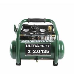
My compressor came from Menards (not this exact one, but real close):

For a first airbrush, I would recommend the Badger 350. Simple to use and clean, lays down paint well. It's not going to give you super fine details like an an expensive double action brush will, but for the majority of model work it will do just fine. You can get new ones from eBay for $40-50.

Don's Airbrush page has a lot of good info as well:

I like to tell people "It's amazing what you can do when you don't know what you can't do."
I'm willing to bet you can do a lot more than you suspect you can. You've just got to give it a try.
 
I marvel at you modelers that can do stuff like this. I would have this thing so clustered up by now
Mike, even I've managed to do this reasonably well after only a few days practice, just don't make the mistakes I made.

1) Don't get a diaphragm compressor.
2) Don't buy a $10 Airbrush
3) Do buy some cheap (broken even) cars to practice on.

For paints and tips check out TomO's weathering thread.
After that, you'll be golden mate.


Back
Top