Building a layout from scratch (Need Advice)


level42

Member
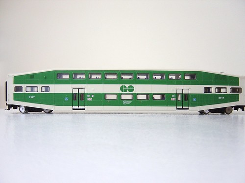
I'm about to start my layout, I'm going to be running 2 trains, a 10 car Go Transit and an 8 car Via Rail. They will be parrallel lines running in my bed room along the wall. There is going to be all 4 walls covered in a shelf like layout except where the door is.

I have a few questions I'd like to ask and if anyone else would like to shed some insight I'd love to take your advice.

Q. I plan to do an under over set up but due to limited space, I will have the trains start at a "MID" Elevation and 1 line will drop 1.5" and the other will rise 1.5" (Giving a total of 3" clearance in half the space), My question is, how long does the track need to be to achieve this elevation and de-elevation? (I heard a 2% grade ( I.E 100" in length to rise 2" or for my needs 75" long for 1.5" rise, is this correct?)

Q. What type of track should I consider using? I'm looking at about 40' of over length in my layout, which will be a back and forth layout. So far I've considered using Code 100 Atlas track. as well as #6 or #8 turnouts (Can anyone suggest anything better or different considering the trains I will be running?

Q. Should I use small 9" segments for the straight sections or should I just use 3' flex track, which would you consider better? (I wanted to use the 3' flex to eliminate excessive connections for possibilities of derailments) Good idea bad idea?

Q. I will be having 2 lines, the inside curve will be a 22" diamater, what should the diameter of the outside curve be?

Thank you to anyone who takes the time to help me out :) I will add more questions as my layout progressess and I need more help. Thanks again guys :)
 
1: 1.5/75 = 0.02. You are correct! You can get away with is being a steeper grade if necessary.

2: Atlas Code 100 would probably be the cheapest route. #8 switches will look better, but #6 will work fine.

3: Use flex track! You are right about having fewer joints.

4: I'm guess a bit here, but I'd say 24.5" should be okay. To be safe, you'll want to lay this out and put your longest cars on each track to see if there is clearance.

Kerry

Thats great Kerry, Thanks.

As per the 75" distance for the incline, I won't be going shorter because its such a long and heavy train. 10 of these:
3880529057_0faa2b58b1.jpg

plus a dummy F59PH

I will be using the #8 turnouts, given that I have the space on my layout to do so.

Aswell, for the 24.5" radius, obviously there are no preformed turn segmets, I'd have to make this out of flex, correct?
 
How wide is the widest point of your layout? That will determine your maximum radius. For example, a 4' wide segment will have a maximum radius of 22". The wider you can make the turn radius, the better, since you'll be running nothing but long passenger cars. Using flex track will give you the widest possible without having to worry about standard sectional track radius curves. My preference would be Atlas code 83 track. It looks better and will work as reliably as code 100 with modern models.
 
Hmm, well I was planning on only having the shelf about 6" out from the wall on the striaghts, maybe 8" as per the turns I was kinda hoping to keep them as narrow as possible, due to the extreme space limitations in my room.
 
Or get yourself a wooden yardstick and drill pencil-sized holes in it at various radii. (Yeah, I'm cheap but it works...)
 
OK, a lesson in basic math here. You need twice the radius of a curve to have enough room to lay down the track. For a 22" radius curve, you need 44" but, for practical purposes, you really need 48" so you have two inches away from the edge fo the layout to run the tracks.

Now, if you want to just run a shelf completely around the room, things change. You only need to get the curve so it follows the shelf. You can cut the shelf to follow the curve but you still need space from the wall to the track to make it work. Using the same 22" radius curve, you'd need 12" from the wall plus 2" for the distance from the edge of the shelf to the track. You could then transition back to an 8" straight section of shelf from the curve. as long as you can get about 14" out from the wall in the corners, you can make 22" curves work. You can go down to about 10" from the wall and 6" straight sections if you're willing to live with 18" radius curves. The laws of space and mathematics still operate in the minature world so 6" to 8" shelves are not going to allow you much of a curve. This would be an ideal situation for N scale, assuming you don't already have the equipment bought and that it's available in N scale.
 
So, 14" that would be from the corner of the wall, to the apex of the corner?
See Diagram

Also, I've been playing with a few Model train layout softwares, and no matter what, I can never seem to get both ends of the (22 and 24.5 inch turns) to meet at the other end sparing the same distance apart. See diagram

I hope its clear enough that you can understand.


Thanks for all your help so far :)
 
you getting some good feedback.

one thing that i would add is suggestion to pay bit extra and go with better turnouts. walthers/shinohara turnouts are good but they are code 83 (which that what i'd use if i to start over today). switched from atlas to peco and the only question i had for myself is why i didn't go with them from the get go.
 
Yes, the part of the wall called out as 14" is the space you'd need for a 22" curve. I really think you are making a mistake trying to run any double track in such a small space. You'll end up taking up half the room for the corners to get a 24" or larger curve on the inside track. The spacing on the curve between tracks is normal. You must have more space between the apex of the curve and the transition back to the straight section to keep cars form hitting each other in the curve. You can experiment with flex track to get this spacing down to a minimum, but two lines will bring your corners out to about 30". If you have that much room, no problem, but it sounds like you're pressed for space. You have plenty of space on the straight sections to add sidings, so you can run two trains, you just have to have one take the siding so the other can pass. I'd go this route and save the big double track mainline until I had a lot more space.
 
I had such an elaborate plan in my head, and I can see it in my head, however, I've never actually gotten around to getting proper measurments.

**Note my layout is NOT! a completed loop, but a back and forth layout.

Everything has been done by simply guessing and estimating in my head. I guess I should plan it out and draw it up to see how well it would fit, now I don't recall mentioning this but maybe I did.

I was planing to aswell have an under/over part. The Dimensions of my room (are approximate) 10' X 9' X 12' X 9'. With my estimation in order to raise the track the full 3" at a 2% grade I'd need an over all distance of 150" on both sides. 300" = 25'! Clearly this wouldn't fit. I decided to start the train at a 1.5" height and make the train either increase 1.5" or decrease 1.5", thus cutting the incline distace to only 150" for both sides (I.E 12.5') On top of that, I'd need to consider the length of my two trains (10 car Go, and 8 car via) These will require almost 12' of excess track at each end plus about 2' for switches at each end.

This brings my grand total of distance in track to approx about 40.5' and my wall perimiter = approx 40' (I figure I couold squeaze it in)

I'm sure it's probably not going to fit but I sure hope it does. (And I really don't want to shorten the lenght of my train, Go Transit never runs less then 10 cars)

Idealy, I'd like Go at one end and Via at the other, they would run on individual lines passing each other with one going over and one going under.

Once they both reach the other end, they would carry on back again, but switching sides via the 2' of designated switches.

I hope I'm making this as clear as possible.
 
If you use Code 83, Atlas now has 24" radius track in packs. If you don't want to mess with yardstick trammels, get some of this, especially if your layout is small and doesn't have a lot of curves.
 
I built a layout in a similar situation, which led to an unusual solution. The room had doors on two opposing walls. One door, seldom opened, had a bridge mounted to it with a swing-up short section at the hinge jamb. I had to slide the rail joiners into place each time it opened. The other doorway was in constant use, and could not be blocked. It had a lift-out bridge until my son grew tall enough to bump his head then it came out. Then I had to innovate. I changed the layout to a point-to-point single track with a return loop at each end. This track was divided into three blocks. The center block consisted of the single track and both turnouts. The diverting tracks were connected to the loops with insulated rail joiners. The loops were wired fixed, meaning the outside rail of one loop was always positive while the outside rail of the other was always negative. Magnetic reed switches let into the ties were activated by magnets under Steam Tenders or certain freight cars placed directly behind diesels. Passing over a reed switch coming out of either loop fired relays that closed and sent current to : (1) align both turnouts simultaneously while (2) flipping the polarity in the center block for the engine which is now reversed in direction. The polarity in the center was flipped by an Atlas Snap Relay. The turnouts were Atlas Custom-line. The relays and reed switches came from my automatic door trade, but are available several places, maybe Radio Shack. This wiring plan would allow you to have only two single tracks at the central station, if you desire to save space along the walls. This was a lot to do with dinosaur components. It would be nice if someone with solid-state design experience (Help!) could draw this up so that the magnet/reed switches were replaced by a more modern proximity device; the center block polarity was reversed by a chip or something; nice, too would be terminals for appropriate block and dwarf turnout signals. They add a lot to the layout appeal.


Back
Top