Beginner Seeking Guidance on New Layout


Tim001

New Member
Hi Everyone,
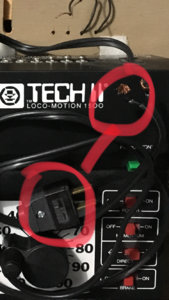
I was wondering if I could get a little guidance and pointed in the right diriection. My family recently won at a raffle an amazing layout that was donated to a club at a show we recently went to. We are extremely thrilled and my kids are over the moon. Models are a bit new to me but I’m excited for my son and I to do a lot of learning. I’m wondering if someone could shed some light on this configuration and some guidance on setting this up. It’s in running condition (it was running at the show) just not sure the correct way to plug the controllers in. Below is my mock up of the control panel and how the wires are connected and how I believe I should be connecting into the two controller packs. However, I’m very confused, when taking the controllers out of the box the prongs were unscrewed leaving the wires exposed, leading me unsure why that was done and if they should not be plugged into regular wall outlette. Any tips? Thought on the layout and equipment? Guidance? The last thing I want to do I break anything on this beauty.
1A5387B7-5C8A-483E-A0BE-7D26C80FF3EE.jpeg
D6082AE3-60CB-4157-A20E-F26553E761F3.jpeg16644FBA-E8A4-419C-927F-2842AB564385.jpegB5BA18F1-E0A0-4990-B85E-FFDE066A06A0.jpegCB07A336-8A5B-4A4B-BDF0-78814CD131E7.jpeg
 
Well the switch (turn out) control is the two rows of switches on the right under the drawing of the layout in the upper photo. And the bank of switches to the left in the upper photo control with piece of track gets the power. The red lines mean nothing to me. Now your problem comes in the hook up of the power pack. The switches to the left will get track power from the controller and the bank of switches to the right need steady power not from the controller. Any lights on the layout need steady power, probably AC. More than that, I can't help you with out seeing the layout. :)
 
The wires to the two banks of switch controllers connect to the two right hand screws in picture # 5. The two left hand screws are track power and are controlled by the dial controller; one connects to the upper left screw on the middle bank of "Selectors", which control which section of track gets power by sliding the green slide switches up; the other wire from the left screws is connected directly (or indirectly) to the track as the "common" wire. The lower left hand screw on the "Selectors" connects to a second power source so you can run two trains on separate sections at the same time, it controls sections powered when the green slide switch is down. Center position is off. It is common, although not necessary, to supply power to the bank of switch controllers from a different power source or else there's a momentary slow-down in train speed everytime that you "flip a switch". Lights and accesseries can be controlled by the center two screws on the power source, although like the switches, will do better on their own supply.
 
Whoever cut the plugs off the power packs wasn't thinking very clearly. Especially considering that the layout may have been built with the express purpose of giving away in some type of drawing! If you know how to install new plugs that would be the logical next sequence to getting the railroad up and running. If you do not know how, take the power packs to someone who can help you.
 
Thanks everyone for the feedback! Looks like I’m on the right track ;) ! I’m going to work on testing it in the next day or so and will let everyone know how it goes.

For the power packs I do have the detached plugs. Looks like someone just unscrewed them - see attached.
 

Attachments

  • 9E53F7C1-8C26-4D6C-9371-23826B58B0BF.jpeg
    9E53F7C1-8C26-4D6C-9371-23826B58B0BF.jpeg
    821.3 KB · Views: 160
Hi All,
I was able to get everything hooked up, was up until 1am last night! Now for ironing out some kinks. The trains run very poorly and only at full throttle and the lights flicker as they are running. I tried a couple engines and they won’t run at low speeds. I checked the track and at full throttle the tracks are getting about 19v DC does that sound correct. This leads me to believe the issue is that the tracks need some very good cleaning, as this layout had probably been used for quite some time (owner passed away which is why it was raffled by the clubs). Any other thoughts? Anything else I should test from a electrical standpoint? This evening I’m going to swing by my local train shop to see what type of cleaning products/tools they have and hopefully that works. Thank for the help everyone!
 
Aside of cleaning the track which is very straight forward the locomotive itself likely requires good cleaning of the wheelsets and/or contactors.

Alcohol and cotton swabs are the tools, the challenge would be to disassemble the engine to be able to get to all the parts. Will depend on what specific engine you have.


Back
Top