
You are using an out of date browser. It may not display this or other websites correctly.
You should upgrade or use an alternative browser.
You should upgrade or use an alternative browser.
A basic question from a newbie re radiuses.. (Radii??)
- Thread starter Skip
- Start date
Skip
New Member
I'll try to take some pictures of my Polish engineering drop bridge for you when I get home if you're interested.
Sure, thanks. I can use all the help I can get on this. I'll also look up some articles onna web and see what I can find.
Regards,
Skip ;>})
montanan
Whiskey Merchant
Here you go Skip, here's the Polish engineering bridge. The bridge itself is 5/8 plywood. That's what I had on hand while building the layout. It was going to be temporary when it was put in about 25 years ago, but it has been working just fine for all these years so it stayed. If it ain't broke, DON'T FIX IT.
 Here it is in the up position. Click on the picture to enlarge it if you want. These tracks are for my hidden staging area.


These two pictures show the hinged end. There will not be any allignment problems on this end. Feeder wires for power are in the next picture. they were just soldered to the corresponding rails.

For the other end, I used a couple of cabinet slid bolts to lock the bridge in place when it is up. Once the flex track was installed on the bridge part of the layout, the bridge was left up and I used a couple of scraps of plywood installed at a slight angle to make sure that the tracks would align.
I have to make another post to get the last two photos in........ To be continued.
Here it is in the up position. Click on the picture to enlarge it if you want. These tracks are for my hidden staging area. These two pictures show the hinged end. There will not be any allignment problems on this end. Feeder wires for power are in the next picture. they were just soldered to the corresponding rails.
For the other end, I used a couple of cabinet slid bolts to lock the bridge in place when it is up. Once the flex track was installed on the bridge part of the layout, the bridge was left up and I used a couple of scraps of plywood installed at a slight angle to make sure that the tracks would align.
I have to make another post to get the last two photos in........ To be continued.
Last edited by a moderator:
montanan
Whiskey Merchant
Here are the last two photos. You can see in the second photo where the scraps of plywood will keep the tracks at the open end aligned.


If you are worried about warping, you could tack and glue a couple of 2 inch pieces of masonite to the side of the bridge on the upper side which would also act as a guardrail.
Like I said, it was going to be temporary until I came up with something better, but it ended up not having to be improved for my purposes. It ain't pretty, but it is functional.
Skip
New Member
Hi
That's a neat looking layout design. Can you tell me what radius those sweeping wide curves are? I'd like to snake tracks in closer "S" curves around that bow area but I'm not sure if the radiuse's involved to do this would be acceptable? Remember, I'm quite okay in my thinking with 18" and 22" radiuse's...
Thanks,
Skip
Skip
New Member
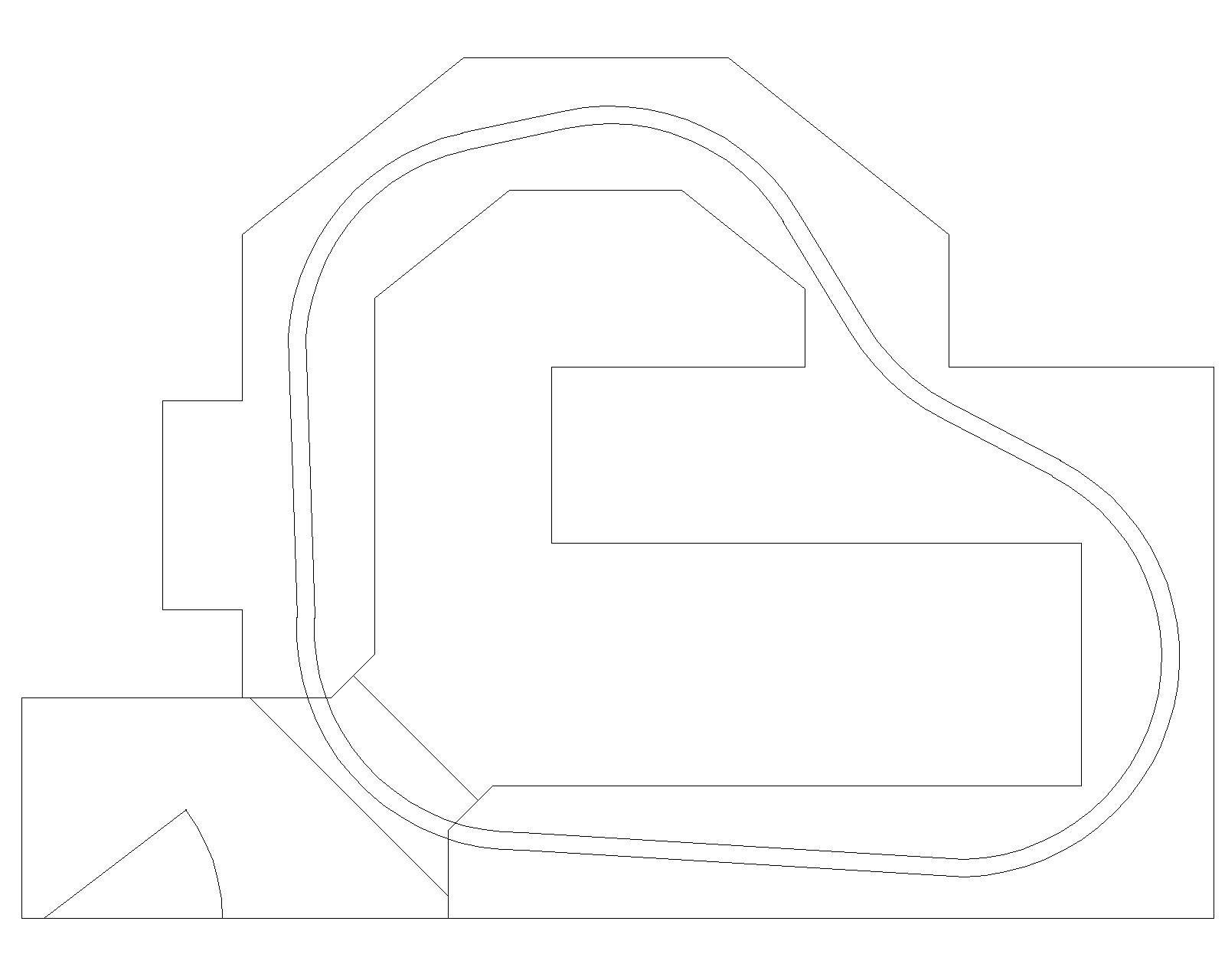
I drew up your room in autocad and tried to layout a folded dog bone. There is really not enough room to do it. I agree with Montanan that a shelf layout around the perimeter is your best solution.
Steve
Hi Steve
When you say there's not enough room, I'm curious about this... When I measured the room it appeared to me to fit two 22" radius loops at the widest part's sides while still leaving an 18-20" pass thru to the room's center? I'm not at all familiar with autocad, but does it work on the parameters one enters? If so do you think two dog bone loops might work if you entered something that said use a maximum 22" radius? I know this would probably use up more room space, but then it might also allow some yard storage in the center of the loops?
Thanks,
Skip
{I guess I'm still being a bit stubborn about those dog loops... ;>})
Skip
New Member
I used a 28" minimum radii on the plan. When I try to draw the dogbone style layout you end up needing almost solid bench work on either end of the room. This creates bad reach issues. It can be done but will not be ideal.
Steve.
Thank you Steve... So if I go with a minimum 22" radius I believe that would probably give me enough room to navigate in the center of the room between the two reverse loops? And then at that it should only be tight in the one spot, as the rest of the layout would be shelf-like, around the room.
If you have the time, I'd be very interested to see what your CAD dogbone design for my available room might look like in the smaller radius's? I'm really trying to keep this layout very simple {and very quick and easy}, and I would appreciate it if you would use your CAD skills to show how much empty center space I would get with less wide curves?.
For instance I'm planning to use some existing bookcases and storage basket cabinets as supports for the plywood platform{s}, with height adjusting shims screwed into the platforms and then into the tops of the wooden cabinets, so I'll have platform supports that are also roomy train and gear holders.
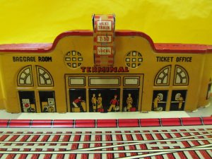
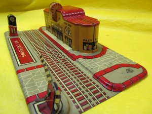
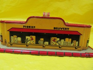
My thinking about HO layouts might startle some MRR magazine-reading folks, as I'm not looking to emulate a realistic looking miniature world but am instead very much into "toy stuff" even with HO? My initial plywood platform coverings will probably be indoor-outdoor green carpeting with black rubber roadbeds under code 100 flextrack, and my train stations are some lovely (IMO anyway) Marx lithographed tin ones that are (mistakenly?) more HO size than 027. In my HO world I'm mixing the highly detailed HO locos and rolling stock that I love with some toy surroundings, in much the same way I like to mix my impressionist Marx 027 toy trains with some realistic surroundings. {I've attached a photo that shows some beautiful HO Atlas ATSF heavyweight varnish standing in front of a Marx tin station so you can see what I like...;>})

Attachments


Whatever boils your egg 
