Wiring up my n-scale dcc layout


Frank

Active Member
Hi guys, I'm a bit confused about how to wire up my layout. There's about 24' of track crammed into a 3'x2' area with a dozen manual turnouts mostly crammed into 3 areas. I'm planning to use 22 gauge wire for the feeders. Right now I'm using a Bachmann ez command controller if that matters.

I think doing feeders to the ends of each of the sidings, in between the insulated frogs on the turnouts and at each end of those curves on the right and left side of the layout is probably more than enough.

This is part of a modular layout I'm doing. I don't need it to interoperate with other people's layouts, but I do need to be able to add connectors for that at a future date. I'm planning to use 14 gauge wire for the buss wire.

I'm not sure how best to connect the feeder wires onto the buss wire. I don't necessarily mind soldering, but I'll have a lot of wires needing to connect at the same place. And I'm eventually going to be upgrading the turnouts to use tortoise machines.

Hopefully I'm being more clear than a cup of mud.
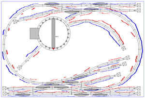
N622NP_3x2_mod_1_wiring.png
 
I think doing feeders to the ends of each of the sidings, in between the insulated frogs on the turnouts.
What kind of turnouts are these? It doesn't matter if the frog is insulated, it only matters if the turnout passes power through all the time (non-power routing). Most turnouts do that.

If this was mine, and unless these are power routed turnouts, I would simply put two wires to the main (orange and green thick), or if I really wanted to do overkill I would put an additional set of wires to the main on opposite sides of the layout (thinner orange and green). But I would use 20 gauge wire not 22. I would not go to all the work of a bus.
wiring.jpg


If the turnouts are power routing, then you need to decide which (if any) of the spurs you want power on all the time and which you don't. That is then what determines where the power would go (in addition to the ones to the main).
 
Last edited:
What kind of turnouts are these? It doesn't matter if the frog is insulated, it only matters if the turnout passes power through (non-power routing). Most turnouts do that.

If this was mine, and unless these are power routed turnouts, I would simply put two wires to the main (orange and green thick), or if I really wanted to do overkill I would put an additional set of wires to the main on opposite sides of the layout (thinner orange and green). But I would use 20 gauge wire not 22. I would not go to all the work of a bus.
SNIP
Thanks.
These are Atlas code 80 switches and don't appear to have any power routing on them. I suppose the easier thing to do would be to just solder a jumper underneath the track to manually route power. I don't appear to have any reversing loops on my layout.

I had the feeling that a buss may be overkill. I've been powering the entire thing via a series of jumpers previously, but now is the time for something a bit more permanent.
 
EDIT: I spoke too soon, I guess these do power route despite what I've read online. I must have been having other issues with the wheels losing contact before. So, I won't bother wiring all of the spurs, and I'll use the terminal strip for connecting my controller to the track and in case I need to use a buss in the future.

With that feedback in mind, I've decided that the least confusing way of doing this is to use a block screw terminal strip to attach things to. And for sanity's sake, I'll just wire up each spur and that should take care of my issues with most of the turnouts not routing power. That leaves just 2 blocks near the bottom that need jumpers or power routing.

Should be easy to do without needing a main buss line, but also make it relatively easy to add should the need arise.
 
Last edited:
EDIT: I spoke too soon, I guess these do power route despite what I've read online.
Hmmm that surprises me. Every Atlas turnout (N, HO, and O) that I've used since the brass ones with fiber ties in the early 60s have not been power routing.
 
Hmmm that surprises me. Every Atlas turnout (N, HO, and O) that I've used since the brass ones with fiber ties in the early 60s have not been power routing.
I need to look into it more thoroughly because I don't see why it's working.

I can't see any reason for the train to be able to make it around the track and onto some sidings. The insulation seems rather complete.
 
I'm not sure if I'm misunderstanding power routing. But, I've taken a picture of the bottom of the turnout and I realize why it's working. I see there's a connection that's hidden under the insulated frog. As you can see under the frog there appears to be some metal. I can't tell for sure, but it does appear to connect the outgoing rail via the points.

Is this normal for Atlas turnouts? Or is this a more recent innovation, because the references I've seen online suggest that you have to manually wire those rails together if you want to pass power.
turnout.jpg
 
Is this normal for Atlas turnouts? Or is this a more recent innovation, because the references I've seen online suggest that you have to manually wire those rails together if you want to pass power.
View attachment 33066
Hmmm, I don't know. Could be a recent change, but the website states "used on thousands of layouts in the last 30 years" which would say not. I would have to get one and do some experiments. Well, … maybe not. I just sent a note to Atlas.
 
Hmmm, I don't know. Could be a recent change, but the website states "used on thousands of layouts in the last 30 years" which would say not. I would have to get one and do some experiments. Well, … maybe not. I just sent a note to Atlas.
Thanks, this kind of puzzles me a bit. But, these are mostly new turnouts, a few were used, but they're mostly ones that I bought new and it doesn't seem to matter whether they had a machine installed or not.

I'll probably just use the power routing that it's got and eventually rig up a switch if I decide to run more than just one train.


Back
Top