Multiple Staging Areas & access to them (perhaps via a 'sub helix')

ModelRailroadForums.com is a free Model Railroad Discussion Forum and photo gallery. We cover all scales and sizes of model railroads. Whether you're a master model railroader or just getting started, you'll find something of interest here.


beiland

Well-Known Member
Angle-iron Brackets made from used Bed Frames

TrainzLuvr

Let me show you what I mean...the black bracket below (top left) was the original design I started with which I actually saw here on MRH, from Bill Brillinger

benchwork%20brackets%20schematic%201.jpg

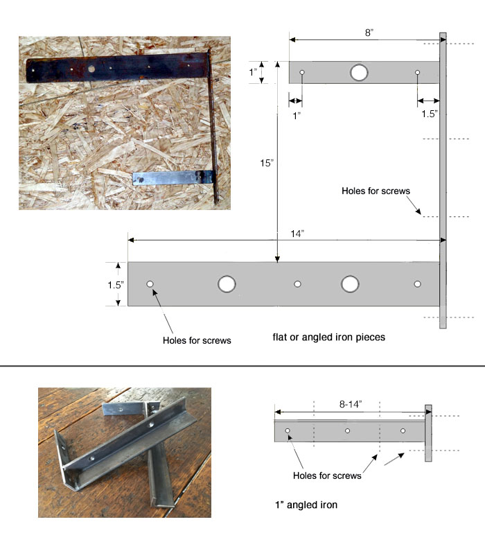
I have now changed my plans, and intend to use some brackets somewhat like you illustrated that were fabricated from angle-iron. I had some 1.5" flange angle iron I salvaged from a metal storage shelf. but I only had just so much of that material, and not enough to make all the brackets I will need.

An Idea popped into my head. Why not just use some angle-iron that can be salvaged off of bed frame mattress supports. Those bed frames are made from some very strong metal that is just the size we need to make brackets,...and they are available real cheap at thrift shops or metal scrap yards.
 

beiland

Well-Known Member
Continous Staging Tracks rather than Dead Ends

By varying the short straight track sections prior to those multiple curves we can get greater spacing between their centerlines, and greater spacing down the 'fairway' (the straight track sections....ha..ha)

DSCF2602%2C%20med%20radius%20switchs%281%29.jpg


DSCF2610%2C%20larger%20centerlines.jpg

My original idea was to have those 2 staging areas on either side of the room, consisting of 5 tracks each, simply extend to the end of the room and dead end there. Staged trains would be backed into each of those 10 tracks (5 tracks x 2 sides), ready to pull out forward and enter the staging access helix to go to the main layout track. That dead end of those tracks would be at the end of the room/shed opposite the helix end of the shed,...that is the door end of the shed.

The gentleman who is welding up my brackets ask me, "why not make another removable bridge across the door entrance to join those two sides of the staging tracks, then the trains could pull forward thru the staging tracks?"

That's not a half bad idea. If I provided such a removable bridge between the dead ends of those 5 tracks down each side, it could offer the alternative to utilize the staging in such a fashion if so chosen in the future. I think I will provide that option.

Drawing to come.
 
Last edited by a moderator:

beiland

Well-Known Member
New Staging Dwg

As I said, drawing to come. Here is my current sketch.

DSCF2642%2C%20better%2C%20ps.jpg


Lets start with getting to the staging area(s). There is a track right next to the wall on the left hand side of the shed at the rear corner that enters the OUTSIDE curve of the track helix. It begins its descent inside the shed just after it crosses over that last major bracket supporting the main level deck. By the time it reaches the 9 o’clock position on the helix it is at a -1.5”. It subsequently drops 1” for each quarter turn around the helix, ending up at -7.5” at the 3 o'clock position, and subsequently -8” at the 3-way turnout at the entrance to the 3 area staging. That is a little less than a 2% grade (1.8% I believe).

Now it can branch out into 3 directions, ...5 tracks on either side, and an undetermined number down under the straight peninsula. At the head of each side track(s) there are 4 Peco medium radius turnouts that feed 5 tracks that ALL make the same 24” inch radius turn into the straight sections of the staging.

DSCF2604%2C%20med%20radius%20switches%281%29.jpg


Those 10 straight sections (5 each side) of staging make turns at their 'tails', and can either dead end at the bracket that is located to either side of the big door, OR there will be a lift-out bridge provide that could connect the 5 tracks continuously. The radius’s on those staging track tails are progressively built in 24”, 26.5”, 29”, 31.5”, and 34” so as to maintain a 2,5” centerline between themselves. Other than in the 4 corners of the layout, the shelf depth required for these generously spaced staging tracks is only 14” from the wall.


The staging level deck will be constructed of the same 3/4” plywood I purchased for the main level deck, and will be supported every 24” by a combination of metal brackets fashioned from the same 2” square, and 1.5” angle iron I am planing on using for the main deck above it. That is probably 'overkill', and the staging areas may just utilize the angle iron material.
Radiata%20Pine%20plywood.jpg

31+BB2Dja6L._AC_US327_QL65_.jpg


Not yet shown in this dwg is a central spine support down the peninsula built of the 2” square tubing to be very minimalistic yet strong.

The helix itself will be 'housed' in a trapezoidal shaped box formed on four sides using some 1.5” square alum sections I salvaged from some screened in porch/pool structure here in Florida. They will intersect with some 64” steel circles I am having bent up from 1.5” angle iron. Those two steel circles (one top, one bottom) will be joined by 12 vertical post made up from 1” square alum sections I salvaged elsewhere. It should be strong, and rigid.
Structural_Shape_Rolling_01.jpg


DSCF1154.jpg

Alum siding will be attached to the outer perimeters of the framing and the top cover. There will be some sort of trap door in the bottom to keep pest out.
 
Last edited by a moderator:

beiland

Well-Known Member
I haven't revisited this subject thread in quite awhile,...because I have been working on the plans, and the helix modification, and start of the helix construction.

For the moment I'll just post this drawing of the 3 zones of staging. There will be 5 tracks to either side of the room/shed. These will be mounted on a 12"-14" board of 3/4 plywood cantilevered off of a very substantial metal framework attached to the 2x4 studs of the shed.

Then there will be 5-6 tracks down the center under the peninsula. These will be off to one side of, and cantilevered to 'metal frame spine' that will support both the peninsula main deck and this staging deck.

DSCF2671%2C%20staging%203%20zones.jpg


...more to come
 

beiland

Well-Known Member
Lower Segments of Helix Structure

The track going down its portion of the helix structure to staging will start its downward path slightly before it exits the left hand rear of the shed, then proceed to utilize the outer loop of trackage to eventually dive under the level balloon loop occupying the inner trackage.

Helix%20to%20Staging%20tracks.jpg


This is the simple level 'balloon loop' just above that helix segment going down to staging. It occupies the inner trackage of the double track helix structure.....

Helix_%20Lower%20Balloon%20Loop.jpg
 

beiland

Well-Known Member
Helix Spiral

For those having a little problem visualizing my multideck spiral within the helix structure, here is another view....
(that B is for 'balloon loop')
helix spiral.jpg
 

beiland

Well-Known Member
Pouring Concrete Pad for Helix Tomorrow

As I have mentioned before I am placing my helix structure external to the rear of my train shed...

DSCF0610%2C%20ps.jpg


Its a big circle having grown to 32.5" & 29.5" radius tracks, making the overall outside dia 69.5". That's coming real close to the power meter pole, particularly as it was leaning forward.

I decided I needed a concrete pad on the ground under the helix, for those times I will have to climb up inside. That's been a lot of fun prepping (just kidding, lots of playing in the dirt and mud of late with our rainy weather). This was just the beginning...

DSCF2688%2C%20ps800.jpg


DSCF2690%2C%20ps800.jpg


Then came the roots,...unbelievable number of roots just under the surface. This photo only represents about a third of them in a 5.5 x 7 foot dig.


DSCF2691%2C%20ps800.jpg


DSCF2692%2C%20ps800.jpg


Then I was trying to prop up and straighten out the leaning power pole, and ended up breaking that water pipe that supplies city water to my house,..ouch !!
Why would they put the water source and the electric source so close together??


DSCF2728%2C%20ps800.jpg


DSCF2729%2C%20ps800.jpg


Will get a final photo of pour site tomorrow morning before concrete partner arrives (leasing mixer, and pouring ourselves).

Guess I better keep that construction hat of mine out a while longer. Is this anyway to build a model railroad????
 

santafewillie

Same Ol' Buzzard
Brian - Hopefully your luck will take a turn for the better. This outside helix thread has kept my interest because that's where mine will have to go if I follow through. Currently I just run two levels as separate branches.

Willie
 

bob

Administrator
Staff member
Brian - Hopefully your luck will take a turn for the better. This outside helix thread has kept my interest because that's where mine will have to go if I follow through. Currently I just run two levels as separate branches.

Willie

How long are your trains and how frequent are they? If they're short and not too many per session, have you considered a "train eater"?

That was a design in an issue of Model Railroader, where it was essentially a rack on the wall with multiple tracks. It would move up and done until the track you wanted was lined up, then you drove the train into it.

You could use the same concept but also have it line up on the lower level. You probably couldn't have as many storage tracks, so it would be more of a "train elevator" but maybe you could have a fair amount, whatever would fit between the floor and the elevation of the lower track.
 

beiland

Well-Known Member
Pour Site ready

This was my final pour site ready this morning.
DSCF2753.JPG


DSCF2754.JPG


My friend and I ended up mixing and pouring 26 bags (60 lbs each) today. I'm worn out and likely sore tomorrow.

I was even having second thoughts this morning about this effort to put a pad under the helix structure, but then I remembered that another reason for doing so was to have a good tie-down structure for that hanging helix in our sometimes stormy location (2 close hurricanes in this last 2 years).
 

beiland

Well-Known Member
Helix Rings,....steel or alum

They will intersect with some 68” steel circles I am having bent up from 1.5” angle iron. Those two steel circles (one top, one bottom) will be joined by 12 vertical post made up from 1” square alum sections I salvaged elsewhere. It should be strong, and rigid.​
Structural_Shape_Rolling_01.jpg


Regrettably I was not able to find a fabricator to make these steel rings of angle iron and/or at a reasonable price. So I had to settle to some rings bent of 2"x1/4" thick aluminum beam. They arrived a couple of days ago, and I'll start some drilling work on them tomorrow.
DSCF2743.JPG


Sure look bigger in real life, particularly when standing on edge.

DSCF2742.JPG


DSCF2744.JPG
 
Last edited:

beiland

Well-Known Member
So here are the two alum rigs set up on my caster work table getting inspected for roundness, and marked up for drilling holes for the upright pieces that will connect the two.

The subcontractor shop did a great job in giving me my exact requested dimension of 69.5" inside dia, but the alum material without the extra flange has to be coaxed into absolute roundness by itself. But other additions will take care of this.


DSCF2751.JPG


DSCF2752.JPG
 

beiland

Well-Known Member
Helix Roadbed

Several weeks ago we began to cut out the roadbed I will be using for my helix. We set up a production site on my castered work table to make use of a router to cut the arcs of the roadbed. The roadbeds are mostly 6" wide to accommodate the double radius tracks. There are some single track roadbed pieces that are 3" wide.

The outer radius of the roadbed is 34" so it turned out quite good that I could just barely get a full quarter-circle piece of roadbed out of the 4 foot width of masonite hardboard. that allowed me to get a surprising 11 pieces of 6" wide, quarter-circles cut out of a 4' x 8' sheet of masonite.

DSCF2653.JPG


DSCF2656.JPG


DSCF2657.JPG


DSCF2659.JPG


DSCF2666.JPG


DSCF2667.JPG


Very little waste out of the 4' x 8' sheet,...
DSCF2664.JPG


Since I am using a double layer of the 1/4 masonite, we cut most of these quarter circles out of the 4' x 8' sheets doubled up. Sure was a dusty mess!
 

beiland

Well-Known Member
Glued & Sealed


During this past week we had rain almost everyday. I was really concerned with my roadbed getting wet prior to my glueing and sealing of them.

Glue
My builder friend highly suggested that i utilize a wood glue called Titebond II to glue the double thickness of masonite roadbed together. He has a long history of using this product in home counter projects etc. At first I thought the product might be a little to 'liquidy'. I was wrong. it turned out to be just the correct consistency. We had a small plastic roller that was idea for applying the glue. I applied the glue to the rough side of the masonite, then placed the smooth side of the adjoining piece to it. We also staggered the joints by 3" to provide for the future joining of the curves to one another to form the complete circles. The 3' was deemed adequate as each of the joints is located at the metal braces that will support the roadbed from underneath.

Its surprising how stiff this double layer of masonite hardboard is. It may be possible that i will not have to provide the 16 metal supports I have available around that full 5 foot circle. Perhaps I might only have to use half of them, 8?? We will see as initially I plan on installing only 8 supports,...BUT all of the support locations will be pre-drilled to easily install the other supports if deemed necessary.


Seal Masonite
My next concern was sealing that masonite from moisture absorption. I had purchased some HD sealer that was designed for massonary/brick/concrete from a fellow on craigslist. i started out painting two quarter circle pieces, but became alarmed at how 'gritty' this paint was. It was almost like it had sand in it, or some kind of non-skid !! The seller had never mentioned this. I stopped to let it dry until the next day. UNACCEPTABLE.

I needed to get all these quarter circles sealed up as quickly as possible as we had big rain storms coming this weekend, and humidity levels were rising quickly. Since I was concerned with color, I shopped a few local big box stores for the mi-mached paint. Found a couple of gals, mixed them together and painted all thepieces yesterday before the rains.

DSCF2755.JPG


DSCF2756.JPG


DSCF2757.JPG
 

migalyto

Well-Known Member
Just caught up with this thread. Quite a project you have going there. Looks like you have put a ton of thought in this.
 

beiland

Well-Known Member
Frame Mock-up


Between the rain storms to day I decided to do a little mock up of the framing I want to use to enclose the helix loop. Of course things are just laid out down on my new concrete pad. The helix structure will be about 33 inches higher than this 'ground view'.

The frames are 2" square alum tubes utilized in a lot of porch screening down here in FL. They will surround the helix ring, and lend support for the metal wall sheets enclosing the helix.

i wanted to see how it looked in general, and how close it all came to that power pole.

DSCF2758.JPG
 

beiland

Well-Known Member
Now I just have to get all those track penetrations thru the back wall of the shed correctly located.
 

santafewillie

Same Ol' Buzzard
How long are your trains and how frequent are they? If they're short and not too many per session, have you considered a "train eater"?

That was a design in an issue of Model Railroader, where it was essentially a rack on the wall with multiple tracks. It would move up and done until the track you wanted was lined up, then you drove the train into it.

You could use the same concept but also have it line up on the lower level. You probably couldn't have as many storage tracks, so it would be more of a "train elevator" but maybe you could have a fair amount, whatever would fit between the floor and the elevation of the lower track.
Bob - Just saw this, sorry I didn't respond earlier. All of my trains are between 20 and 24 cars long because that's how long most of my passing sidings are. I have seen a train elevator in person on a layout that I visited on a home layout tour, however it's not something that I would tackle. My original intent was to build a helix outside the train room on a covered porch, in a 5' x 8' space...oval shape with most of the rise on the straight sides. Still is the plan, just haven't gotten there yet. The cutoffs in the mains are there and are temporarily used as industry sidings to low relief structures. However I am happy running the layout(s) the way they are right now (165' of main line on each level; 35+ industries per level), and scenery is a much more important use of my time at this point. Some day!:p
Hey Brian, sorry for hijacking your thread.

Willie
 

beiland

Well-Known Member
..... However I am happy running the layout(s) the way they are right now (165' of main line on each level; 35+ industries per level), and scenery is a much more important use of my time at this point. Some day!:p
Hey Brian, sorry for hijacking your thread.

Willie

No problem Willie.
Is there a link to photos of your layout?
 

santafewillie

Same Ol' Buzzard
No problem Willie.
Is there a link to photos of your layout?
I have no links to photos. I don't do social media so no gallery. I do not have enough finished scenery completed for any good overall shots; however, I posted over three dozen shots of individual structures only, over in the Running Bear's Coffee Shop May 2018 thread.
http://www.modelrailroadforums.com/forum/index.php?threads/running-bears-coffee-shop-may-2018.30288/
There's also another dozen or so at the end of the previous Coffee Shop, Running Bear's LXXIII Coffee Shop, starting on page 74.
http://www.modelrailroadforums.com/...unning-bears-lxxiii-coffee-shop.30084/page-74
I don't think that individual galleries can be set up on this forum. I can only post under general categories.
Some day I will take pictures of some of the railroad itself, if I can quit running trains long enough. LOL

Willie

EDIT: - I just went back over to the photo galleries and it indeed looks like I can set up an individual gallery. I will look into it and get something going.

Willie


Affiliate Disclosure: We may receive a commision from some of the links and ads shown on this website (Learn More Here)


ModelRailroadForums.com is a participant in the Amazon Services LLC Associates Program, an affiliate advertising program designed to provide a means for sites to earn advertising fees by advertising and linking to amazon.com

RailroadBookstore.com - An online railroad bookstore featuring a curated selection of new and used railroad books. Railroad pictorials, railroad history, steam locomotives, passenger trains, modern railroading. Hundreds of titles available, most at discount prices! We also have a video and children's book section.

ModelRailroadBookstore.com - An online model railroad bookstore featuring a curated selection of new and used books. Layout design, track plans, scenery and structure building, wiring, DCC, Tinplate, Toy Trains, Price Guides and more.

Top