Manual Turnout Control by Cable


Why I am now backing away from this 'on-the-deck' cable system idea

1) Installation problems, and 2) Maintenance/Repair perceived problems

Lets see if I can describe the installation problems correctly. I'm laying down my cork roadbed, and track, and turnouts, exactly as I had drawn out on my brown paper pattern, while concurrently removing the paper pattern, then glueing the cork down. At this point in order to stick to my tightly configured plan I would like to glue down as much track as I could,....at least the ordinary track existing between the turnouts, as I am NOT wishing to glue the turnouts themselves down,...a no, no as I understand it.

BUT I can't really glue any of the track down yet due to 2 factors,..I have yet to cut all those slots in the roadbed for subsequent control cable routing,...and I have yet to sand/rasp those ramp areas where the cork is changing height from mainline height to yard or sidetrack heights. That cable connection to the turnouts looked so simple,..
image-20201110095313-2.jpeg


..but then my thoughts turned to having to plan out ALL of those cables routes and cut the slots under each turnout bar, AND under subsequent roadbeds the cable would route under other tracks leading to the edge of the deck,....all before I could absolutely glue down the tracks and turnouts.
image%2843%29.png


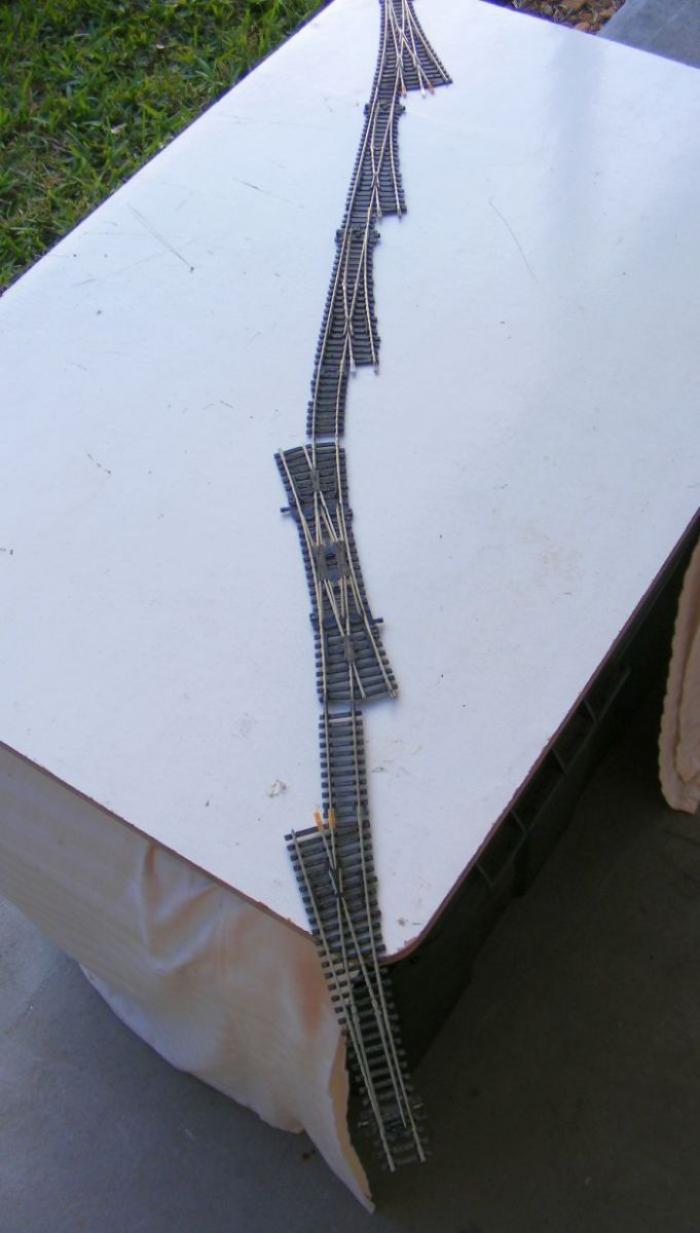
So before I could fastened down any of my track. I was going to have to connect all of those control cables to their respective turnouts and leave them lay across other trackways until I could get to them. And I was going to have to be careful keeping them all inserted up UNDER their throwbars in unison,...and particularly when I had a whole chain of them such as in a ladder situation like this,..


TOO CONFUSING, PROBLEMATIC, etc !!
...(and it had me thinking about repair/maintenance/replacement of any one of those turnouts)


So I'm going back to this idea,..
“I would like to place my tracks and turnouts down and tweak their alignments, BEFORE I have to provide that hole for the vertical rod. Only then would I need to drill that hole for the vertical tube that will house that vertical post. That tube will be a tight fit in the ¾' thick plywood, and allow the free rotation of that vertical rod/post.”


So my control cables/rods will be below decks, BUT the piano wire rod/wire that actually moves the switch throwbars will be (installed) dropped in from the top,...similar to this
https://model-railroad-hobbyist.com/node/40133?page=3#comment-447725
 
Over the past week i have been experimenting with manual control of crossovers. All the while i have been thinking of how I might end up cable controlling my just ordinary single Peco turnouts. I've vacillated back and forth with various ideas until I practically settled on this idea of on-the-deck surface mounting discussed here,..LINK


I actually went forward with this idea and ordered a bunch of the plastic tubing and .047" music wire. But as I played with the idea of routing all those cables under the intervening tracks, etc. I went back to ideas involving under deck cables. Most of those usually involve some sort of rotation motion via a vertical wire within a tube up to the turnout. Nothing was really exciting me as the most simply method.


I then went back to the simple idea of a 90 degree bend in the .047" music wire up thru a hole on the plywood deck, and into the hole in the turnout throw bar. The 'guide tube' for the control cable could be plastic or metal that would be glued directly to the underside of the plywood deck,..dead simple, no rotation gadgets.


I tried it out here in two places,...in one case its that small music wire inside the small plastic tubing I had purchased earlier, and in the second case I used some evergreen plastic tubing as a 'guide tube'. Both worked just fine.


image%28110%29.png


image%28111%29.png


The one pain-in-the-behind is trying to get that little small diameter music wire up thru the turnout throwbar, particularly if the turnout is already mounted,...(may have another solution here?)
 
Another Variation

I moved on down that side of the layout to a corner that will have my coke plant and power plant. It has a number of turnouts that become a little difficult to finger flick as they are over behind my stone viaduct. Even though they are a short distance away for my extra long arms (36" sleeve), I saw it as a challenge to make them operate via some sort of control at the aisle's edge.
My first thought was to do something like those other 2 singles I had recently done with a music wire up thru the throwbar from under the deck. BUT,... in this corner I had a few obstacles on the underside of the deck,...the metal box framing of my benchwork, and extra plywood bracing between individual plywood deck pieces,...making underdeck cable control much less appetizing.
image-20210127205758-1.jpeg

image-20210127205828-2.jpeg


Here is that corner with the viaduct set in place over the new 'channels' I have provided for the 'on-the-top-of-the-deck' control cables.
image-20210127205916-3.jpeg


Those are the plastic tubes that guide the .047” music wire to the turnout throwbar. They sit in a shallow channel that I cut into the surface with a small router I borrowed from a friend.
image-20210127205957-4.jpeg

image-20210127210043-5.jpeg


The music wire inside that protective tube will be flush with the plywood surface, thus all the intervening tracks and the piers of the via-duct will not be interfered with. The music wire itself will have a small Z shaped end that engages the throwbar of the turnout.


Brian
 
Hi

Running all those little channels looks like a big job. I think you were onto something previously. I think an under the table connecting cable or rod would be fast, easier, and straightforward.

Thread your preformed top end through the sleeve then bend the bottom at a right angle in the direction perpendicular to where you want your connecting rod. Trim it far enough away from the swivel point that you have some travel.

cross section of switch mechanism.png


I will watch

Dave
 
Dave, thanks for your question and your diagram.

Lets see if I can explain this special situation I had with these 5 turnouts in this particular corner. First off 3 of them were directly located over that 2" steel box beam of my layout 'benchwork'. In other words I could not locate a vertical receptor tube as you pictured, under those 3 turnouts.

These are those 3 turnouts, 2 of them are right along the wall that the beam is mounted to, and the third one is over a major cross beam across the entire room...
1611881591072.png


cross beam & wall beams
1611882804090.png


The fourth one further down the line (to the left) was very close to that crossbeam, and could have presented a problem with routing a underdeck control rod to it.

My thoughts then turned to this alternate 'on the deck' solution, and I figured I would make all 5 the same.

I had already considered such an on-the-deck' idea, and rejected doing it for the whole layout, but it did seem appropriate here.
 
@dave, Per your diagram let me ask a few questions that I have been mulling over for quite some time. I'm using music wire (very stiff wire) because of many recommendations from others. But have you tried to get that nice 90 degree bend in such wire right under the deck, and right at the bottom end of that receptor tube? Can you get a bending tool in there? I might note that you need to get the bend very close to the end of the tube, so that the contained control wire doesn't rise up excessively and trip the train coupler pins running above, or even snare a track cleaning roller??

The other thing that has been concerning me is 'what or how' am I going to make that connection you circled,...between the music wire and the control cable? Lots of ideas have been presented, but they all seem to get into excessive little extra parts. That is what caused me to move away from this 'rotation scheme' to a straight linear control of the turnout's throwbar with the 'bent-up end' in the music wire,...and only a guide tube glued to the underside of the deck next to the vertical hole leading up to the turnout's throwbar. It seems to simplify things to me?.
 
Last edited:
Brian , they make a special set of pliers that will put in a perfect Z bend . It makes both bends at once . You can purchase them at Tower Hobbies ( along with all the assorted parts you may need ) . I think you will find that if you work from the switch to the fascia , rather than from the fascia to the switch , that will take care of many of the problems you just asked about .
 
Brian , they make a special set of pliers that will put in a perfect Z bend . It makes both bends at once . You can purchase them at Tower Hobbies ( along with all the assorted parts you may need ) . I think you will find that if you work from the switch to the fascia , rather than from the fascia to the switch , that will take care of many of the problems you just asked about .
I will have to try and find that tool you referred to, I've not seen it.

I've got this tool that makes a very nice Z-bend, all in one motion,......
https://www.dubro.com/products/e-z-bender-wire-forming-tool
.....but it needs to be vice mounted to work well, AND I don't see how I could make that bend at the bottom of the vertical tube with this tool?
I am going to use to to put the Z-bends in the music wire where it attaches to the throwbar of the Peco turnout.

I thought I was working from the switch to the fascia by attaching the music wire with its Z-bent end into the throwbar, then sliding on the plastic tube housing, then laying that in the trench, then tacking down the switch?

I imagine you are talking about this type of pliers ?,..
1611925769982.png
 
Last edited:
Hi,

I have used a variety of different wires for similar applications. Hardware stores might have some you can feel. I have used electric fence wire and masonry (rebar) wire.

The post above has some nice ones.

Dave
 
Installation Observations

1) I decided against putting Z bends into the music wire where it connects to the throwbar. It was too difficult to coordinate with 5 connected turnouts turnouts with their connected tracks. Instead I am just letting the wires bend up thru the throwbars, then get trim off as necessary.
(I'll like to leave them a little long, and add something to their very tips that would keep them from interfering with any extra low hanging appendages, or track cleaning cars, etc. ANY SUGGESTIONS?) ...(maybe just a dab of epoxy or hot met glue?)
image-20210204100553-1.jpeg

image-20210204100635-2.jpeg

Without the Z bend, this turnout could also be removed if necessary in the future without tearing up the control rod structure.

2) If I were doing this again, I would have made the end of the slot in the wood surface a little more wedge-shaped at the end where it connects to the throwbar,....a little less close tolerance considering the exactness of coordinating all the turnouts in a row.


3) I decided to cut the music wires just short of the edge of the plywood deck so they would not interfere with ongoing construction in the aisle. Subsequently I imagine adding a C-shaped tube onto these wire ends that will closely bend around the edge of the plywood and offer a 'handle' of some sort to control the wire/turnout.
image-20210204101732-3.jpeg


Brian
 
Last edited:
Dave, thanks for your question and your diagram.

Lets see if I can explain this special situation I had with these 5 turnouts in this particular corner. First off 3 of them were directly located over that 2" steel box beam of my layout 'benchwork'. In other words I could not locate a vertical receptor tube as you pictured, under those 3 turnouts.

These are those 3 turnouts, 2 of them are right along the wall that the beam is mounted to, and the third one is over a major cross beam across the entire room...
View attachment 123948


cross beam & wall beams
View attachment 123949

The fourth one further down the line (to the left) was very close to that crossbeam, and could have presented a problem with routing a underdeck control rod to it.

My thoughts then turned to this alternate 'on the deck' solution, and I figured I would make all 5 the same.

I had already considered such an on-the-deck' idea, and rejected doing it for the whole layout, but it did seem appropriate here.


I see why you have to go above board. Looking back, could the benchwork have been built or spaced so as not to interfere with some under the table wires?
 
I was not thinking of the exact track plan when I built the bench work

Metal Benchwork

You might see that my bench work was rather 'unusual',.... o_O ;)

PS: I had to route a few of my feeder wires for that track down along the wall, by way of those multiple holes in the horizontal beam along the wall


Back
Top