How many sound decoders in an F unit consist?


Yannis

Active Member
Hi all,

As the title implies i am after taking some decisions about some F unit consists i plan to convert from DC to DCC.

In particular, all are Genesis units and the two consists i will be having are ABBBA and AABBA. Middle B unit in the consist ABBBA is a dummy.

I was wondering if it is a good idea not to have a sound decoder in every unit and instead do the following:

1. A units having sound decoders, loaded with E8/9 dual 567 sound files, B units having motor only decoders. the odd A unit in the AABBA consist will have a sound decoder loaded with a typical F series single 567 sound file.

2. Another possibility i am considering in addition to point 1. is to add speakers to the B units before/after A units, permanently couple them together and essentially having AB units with 3-4 speakers in total.

These are my thoughts to which i would much appreciate your feedback from similar experiences.

For consists of freight trains with 2 GP units, i plan to have sound in both units so that i can have the freedom to separate them and mix/match at will. The passenger F's though will be more or less in two AB pairs, one B dummy and one A unit.

Based on the above i am trying to see if i can get a more economical and more importantly less power-demanding consist for a 3A DCC system. In the layout i plan to have more or less 2 trains at the same time max. A 2-3 GP freight and the ABBBA passenger with 11 lighted cars (13 cars in total).

Many thanks in advance for your time and replies.
Yannis
 
I have also considered the placement of a speaker installed into a dummy as you are thinking, with a semi permanent coupling (a mini connector for the wires) so they can be split for maintenance. For normal hearing usage i.e. listening to your trains at a walking/standing distance, or even leaning close, it is very hard to detect which is sound equipped in a consist and which is not, but if videoing, particularly close up, the camera microphone will definitely differentiate and record between them.
 
Yannis:

I would consider just installing the sound decoders in the A units of the consists if you plan to separate them and run them in AB configurations and ABBA. Should be no problems with a 3 amp DCC system.

Greg
 
Thank you all for your replies!

Wouldn't having an A unit with sound decoder and speaker with a 2nd speaker coming off into a trailing B unit sound like both units having sound decoders? Especially using the E8/9 dual 567 sound file?

Terry: Do you notice that half of your consist is w/o sound?

I have had experiences with sound in the past but only in single unit ops hence my questions.
 
Aha! I believe the decoder fitted to those locos is actually a dual decoder, not single a decoder with 2 sound files (probably not possible) in order to create that slight out of sync sound, especially at start-up/shutdown and also twin speakers, each powered individually. And probably mounted in the fuel tank. It should still be possible to run wiring to speakers in the silent unit, if there is room for them, but it might be a logistical challenge. If it is as I'm assuming then you would need 2 speakers in your silent unit, wired one to each of the speakers in the sound unit, in series.
 
Thank you all for your replies!

Wouldn't having an A unit with sound decoder and speaker with a 2nd speaker coming off into a trailing B unit sound like both units having sound decoders? Especially using the E8/9 dual 567 sound file?

Terry: Do you notice that half of your consist is w/o sound?

I have had experiences with sound in the past but only in single unit ops hence my questions.
I usually run them as a set, and unless I have a camera at trackside, it's really not noticeable. The "set" is a Genesis F2A/B and Intermountain FT A/B. Originally, the Genesis was DCC ready, and the Intermountains were DCC equipped with no sound. I put a GN1000 in the F2A so I coule get the sound and lighting, and an Econami in the FT B unit, so I could retain the lighting on the FT A. I effectively get 90% of the effects of sound for 50% of the cost.
 
1. A units having sound decoders, loaded with E8/9 dual 567 sound files, B units having motor only decoders. the odd A unit in the AABBA consist will have a sound decoder loaded with a typical F series single 567 sound file.
I understand the concept. But just because the prime movers are 567s the E8s had the V12 model while the F series have a V16, so the sounds aren't the same. Besides that, in my opinion, none of the E unit sound files do a good job of representing two prime movers.

2. Another possibility i am considering in addition to point 1. is to add speakers to the B units before/after A units, permanently couple them together and essentially having AB units with 3-4 speakers in total.
Yes, I think this is the ticket with the lead A units with their own proper F unit sound and draw bar them to the B, have 6 wires between them sets for power, motor, and speaker. AKA Broadway Limited style. The stand alone A is just that. The dummy B should have plenty of sound around it. The issue I've found with these massive hookups like this is making certain the sound from the horn only comes from the front. I've done this, and as toot says I used mini-connectors so they are easier to separate for maintenance.

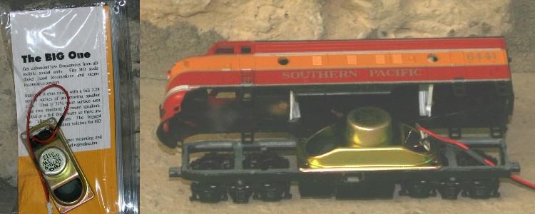
In the old days they used to make sound only decoders that I would put in the dummy B units. Here is my most elaborate one. The white blob on the front is the sound only decoder. All the extra wires and plugs at either end is pass through track power. The whole ABBBA set share common pickup on all 40 wheels. OR the 2nd unit can be just a simple speaker enclosure as the 2nd picture.
StewartSound.JPG
bigspeaker.jpg


Based on the above i am trying to see if i can get a more economical and more importantly less power-demanding consist for a 3A DCC system. In the layout i plan to have more or less 2 trains at the same time max. A 2-3 GP freight and the ABBBA passenger with 11 lighted cars (13 cars in total).
Make certain the lighted cars are with LEDs or that could consume the 3 amps right there.

If you do end up with a mix of decoder types, it becomes essential to do speed curving. I have this issue with a set of three SDP35s. I bought 2 with sound and 1 without. They seem to refuse to run at the same speed(s). It has been a nightmare to speed curving the wo/sound one with the other two so they all run the same. My new philosophy is to not mix decoder types. Soon as I can afford it I am going to just buy a new 3rd unit with the factory sound.
 
Last edited by a moderator:
Terry, Iron Horseman and Beiland thanks a lot for the input.

Iron: You are quite right v12 vs V16, i forgot that. I think i ll go with typical F unit sound file on the A units, use motor only decoder on the B units and at a later stage either upgrade the B units to sound, or add speakers coming off the leading A's.

I am with you on the speed-matching thing. Hopefully my new DCC system will make things much easier / faster to match locomotives (Z21/DR5000).
 
That's the same article I referred to in the Coffee Shop, at least MRH mag has confirmation we're reading it. It shows one of the iP4s speakers opened up and some had cut the size of the enclosure down apparently without much ill effects. I opened a HTC one 8 enclosure and found it to have the extra part of the space almost filled with the same foam as shown in the iP4s. No obvious reason for it, but maybe it does help with the tonal quality.
 
I've seen quite a bit of talk about utilizing I-phone speakers lately,...even beyond sugar-cube ones.
Wouldn't this make it possible to distribute multiple speakers among the loco units real easy??
A few years back I bought a bunch (a gross I think) of the I-phone speakers, to experiment with. And yes, they make working with multiple speakers much easier. I would not go as far as saying real easy. I think it is because of their size the "firing" direction and location is a bit more critical. I have had many, no strike that-, several unsatisfying installations with them. Still lots of research to do and no time to do it.

I did talk to the SoundTraxx people today at the Rocky Mountain Train Collectors Show. They are really going all in on the sugar-cube school of thought. Had examples of various configurations of series and parallel sets of speakers.
 
Last edited by a moderator:
It shows one of the iP4s speakers opened up and some had cut the size of the enclosure down apparently without much ill effects. I opened a HTC one 8 enclosure and found it to have the extra part of the space almost filled with the same foam as shown in the iP4s. No obvious reason for it, but maybe it does help with the tonal quality.
Hmmm, It has been demonstrated for hi-fidelity reproduction, the volume of the enclosure should be equal to a 1/2 multiple of the area of the actual speaker membrane. I wonder if that is what they are doing. My best results seem to keep coming back to 2.5 times. But, the use of foam in speakers has been used for many things besides reducing the enclosure volume. Sometimes it is just used to prevent the enclosure itself from vibrating.
 
Last edited by a moderator:
Hmmm, It has been demonstrated for hi-fidelity reproduction, the volume of the enclosure should be equal to a 1/2 multiple of the area of the actual speaker membrane. I wonder if that is what they are doing. My best results seem to keep coming back to 2.5 times. But, the use of foam in speakers has been used for many things besides reducing the enclosure volume. Sometimes it is just used to prevent the enclosure itself from vibrating.

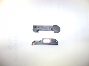
Considering the thinness of the casing walls, antivibration could be the most likely reason for the foam, although it's doesn't appear to be compressed. I would guestimate the enclosure on the HTC one M8 to be something like your 1/2 multiple and the iP4s closer to your 2.5. The diaphram size of the HTC measures close to 12mm X 4mm, not including the pink ring around it, add 1mm if you do. The iP is flat and even thickness of a tad under 5mm, The HTC is thicker at 6mm. The Htc's length is 46mm, or 42 if the fixing tab was removed (Traces ignored as they can be bent out of the way)
DSC05193.JPG
iPhone at top, HTC at bottom

Measurements for iP4s, 53L x 15W x 5 thick. minus gasket
Measurements for HTC one M8, 46 stock, 42 trimmed X 12 wide x 6 thick.

iP4s wire traces much easier to solder wires to and seperate.
 
Last edited by a moderator:
I always thought that the 'sound production' (amount, not necessarily quality) had to do with the amount of the air moved, thus bigger speakers with longer 'good' excursions were more ideal.

These really small cell phone speakers seem to defy that notion? Do they really produce a 'volume' of sound that can be heard over any appreciable distance? Are these Youtube presentations seemingly better as a result of the recording device being located very close the sound origin??
 
...

I did talk to the SoundTraxx people today at the Rocky Mountain Train Collectors Show. They are really going all in on the sugar-cube school of thought. Had examples of various configurations of series and parallel sets of speakers.
I think I remember seeing where an Australian fellow did LOTS of demonstration videos on this subject?
 
I just watched this video of an I-phone speaker installation
[url]https://www.youtube.com/watch?v=jRy4vUt5hh8[/URL]

Several problems I have with this presentation:
1) Too many variables introduced in his presentation,...changing decoders in addition to changing speakers, plus no reference to previous sound (for comparison)
2) He does seem to experiment (or at least let us know he did) with the best orientation of the 'sound slot' of that cell phone speaker??
So did you do ANY experiments on which ideal direction the speaker was oriented? The sound is coming out that slot....correct? So shouldn't it matter what direction that 'sound slot is oriented???


Back
Top