HO Turn Table from Scratch


KB02

Well-Known Member
Alright, since I can't seem to talk myself out of this, and no one else is rushing in to talk me out of it either (thanks a lot guys!), it looks like I am going to try my hand at building a turntable for my layout. This should be entertaining if nothing else. This will be a long term project. I am in the middle of a job change (new job for new year), so my energy might be elsewhere for a little bit in a few weeks. I've got the basics figured out in my head, now I'll see if I can bring them into reality. I need a 100' foot bridge on my turntable, and there are quite a lot of 90' and 130' jobs out there, but not many 100's. The ones I have found are expensive! My theory is that I can build one cheaper than buying one so I am going to try to keep a running tally of material costs, too, to see just how far into debt I go through this project (and if I would have been better off just buying one instead).

Worth a shot, right?

So, to start with, my wife gave me a bunch of modeling supplies for Christmas which included two sheets of 1/4"x4"x3' Balsa and two sheets of 1/8"x4"x3' Balsa. I'm going include that into the total at roughly $5.00. I'm not going to include any tool costs, either, unless there is something super special that I have to get to make this project work.

So, without further delay: Stage One - The bridge!

Starting by cutting out blanks for the bridge side out of the 1/4" balsa:
07A1966F-7B21-4CBE-96C5-3C0DD642261C_zps1yj6gdm6.jpg


Then I drew out the design of the bridge halves on the blanks:
AE4B832A-0713-454C-9429-3CCD99997EEB_zps1xbmjjt5.jpg


Next, cut them out:
96C72B75-1349-400B-A80E-53C14F644956_zpsgputs22b.jpg


I found the best way to do this was to draw out the design on both sides of the blank and then use a straight edge to start cutting the lines on each side. Cutting on one side seemed to cause the wood to cut at a bit of an angle (hence the shavings in the picture).

Interior supports to hold the two sides together out of the 1/8" balsa holding the side at 1/2" apart:
177FB241-30C8-4989-84B2-E83CB5FDB514_zpsb4olsqit.jpg


And Proof of concept for basic bridge design:
CAD5EA98-FDF1-47BF-9D3D-9E7A88862CD2_zpsh2b0wzip.jpg


I am using Atlas Code 100 track. With the 1/2" space between the two 1/4" sides, the track hangs over the edges by about 1/16" on both sides.
6B198DD0-B5A7-46DB-A5B0-CA8A51A0BEDA_zpsuvu6yl7b.jpg


I am going to use some thin birch veneer cut to roughly 5/16" to hang on the edges all around the outside of the bridge to 1.) make up the difference, and 2.) Create the the angle iron look of a real bridge.
0829E912-FAB2-41FD-87F3-82C9538BB224_zpsfjynan5y.jpg


0A363AFA-4826-4956-A14A-C8274690B2D5_zps6fulstzb.jpg


This is where I ran out of steam, so to speak, as I only had the one small strip of veneer to play with. I will need to get some more to finish the bridge. I plan to make small score lines down the sides of the bridge into which I can insert strips of the veneer. Then I will be able to prime it, paint it and weather it (or so the theory goes).

SO: Stage 1 70% complete:
4ECB7309-6420-496C-B585-B217609D791C_zps8rqjeolj.jpg


Stage 2 will be making the pit. I know some great tricks on how to cut prefect circles out of plywood. I have been brain storming and think I have a pretty good idea on how to make it.

Stay tuned....
 
You are making a big mistake doing this !!!!:rolleyes: There now someone officially tried to warn you :) Bridge looks good . The material looks heavy enough that you should not have any movement/warping . Have you figured out yet what the drive mechanism and indexing will be ? I will watch this build with a lot of interest . I just think a transition era road should have a turntable/roundhouse if the room is available .
 
Yes, I too am eagerly awaiting the 'guts' portion of this project. My construction techniques and choice of materials are different but the mechanics are the same no matter what materials are used. Outstanding work on that bridge BTW!
 
Hey off to a great start!
I did manage to find that TT bridge I was talking about, a friend made it some time ago.
It measures fourteen inches, or one hundred scale feet more or less.
Might give you some ideas.

image.jpg

image.jpg
 
You are making a big mistake doing this !!!!:rolleyes: There now someone officially tried to warn you :) Bridge looks good . The material looks heavy enough that you should not have any movement/warping . Have you figured out yet what the drive mechanism and indexing will be ? I will watch this build with a lot of interest . I just think a transition era road should have a turntable/roundhouse if the room is available .

Ha, ha! Thanks for the warning! ;)

As for drive mechanism, my theory is this: I picked one of those ebay auctions a while back for a "Lot of HO Train Stuff." One of the items included was a Jouef powered tender. The poor thing is pretty well beat to the point that its basically just held together by gravity. It does have a nice 5 pole motor in it, though. I figure I can use that for powering the bridge movement. Now I just have to figure out the gearing aspect. I have a spare decoder lying around, so I can just hook that up to it and run it right off my command station. I'll even be able to hook up a few lights and what not should I feel the need to.


Gonna try to sneak out to the crafts store this afternoon and pick up some more veneer and good glue to finish up the bridge. Then hit the building supply shop to get some decent ply to start on the pit.
 
I am going to be modeling the BN and RI in the 70's. I decided to avoid all the issues with a turntable and roundhouse by modeling a filled in pit and a concrete outline of the base of the roundhouse. Then I will build a building over part of it. :D That way I can show the history of the yard. Plus all my freights will be at least 2 units running tail to tail, so no need to turn them.
 
Got some great progress in today on the bridge. Got to Michael's and got the veneer I needed. 1/64" Birch in a 12x24" sheet. Expensive stuff at $20+ a sheet, but the great thing about Michael's is that they list coupon right online every day and you can just show the clerk the one you want to use. I got 50% off and saved over $11.00! :)
AD725AAF-2C33-464C-BB60-1C7BF0DCFBA7_zpsup6des4g.jpg


Got home and started in at it. Took a fine saw and cut score lines into the bridge just big enough to hold the veneer:
004A60E6-CA7B-4C1E-A607-D667E93E40AD_zpsedz1etpa.jpg


Cut strips 5/16" wide for the tops and bottoms and 1/8" wide for the sides. They all stick out from the 1/4" sides about 1/16". Gives it that great angle iron look:
088C0773-D200-4AF0-9B35-5D7E520FE3AC_zpsorat1rwd.jpg


As for the pit, I also stopped by Home Despot and picked up some 1/2" MDF in a 2x4' sheet. My bridge is 14" wide, so the top of the pit will have to have about a 14 1/8" opening. The rim that will old the rail will stick out about an inch from the wall. Doing the math and I will need a 12" circle for the lower half of the pit. The trick that I have used is to make a jig that can be attached to the saw you plan to use (in this case: a jig saw). I marked out the center lines of where the saw would be and the center of the whole. I drilled hole accordingly and attached the jig to the saw. With a corresponding hole in the center of the piece of wood I plan to cut out, I slide a rod in the two holes and start working my way around the circle. I did have to cut a started hole for the saw blade, but that will be easily cover-able. You do have to make sure your blade is sitting at the proper angle or it might want to wonder... (ask me how I know... or look at the circle I cut out).
9D4CD557-C6C9-44C8-B681-B1A1CEAA21F9_zpskzfwghlq.jpg


With a full inch plus on the outside diameter, the plan is to simply raise this section up from underneath wherever it ends up and adjust height as needed from there. From that point I will take more of the veneer to create the side wall.

With the hole cut and a primer coat on the bridge, a test fit to make sure the ledge will stick in far enough, but not too far:
4EE436F3-E7EB-4B3C-A9FB-F7E9307B2743_zpseyunyznn.jpg


The primer help to seal up the wood. I had that "Bright Red" primer for something else. All I can see is the nearly perfect rust color. I then shot it with some flat black to finish the job:
63935908-C721-4E94-BF6E-0BC4836076B7_zps8gh1qdy0.jpg


This is where I really lucked out. You really can't see it too good in the first picture, but the flat black really didn't sink into the angles all that great, but that is perfect as it gives a great looking rusty effect. I basically just hit it with one coat and called it good. I think it turned out great. It looks ever better and brighter in person.
874A1328-8677-45D1-8305-1A1966945C3F_zps865aul8a.jpg


Bridge 90% complete. Comments/suggestions welcome! Next step will be creating the trucks to hold the wheels (the F Unit you can see in the first post will be donating it's wheels for the cause) and then setting the tracks into place. Got a great plan for that, too.

Stay tuned!
 
As for drive mechanism, my theory is this: I picked one of those ebay auctions a while back for a "Lot of HO Train Stuff." One of the items included was a Jouef powered tender. The poor thing is pretty well beat to the point that its basically just held together by gravity. It does have a nice 5 pole motor in it, though. I figure I can use that for powering the bridge movement. Now I just have to figure out the gearing aspect.

some thoughts ...

The Pacific Southern has several turntables.

beneath the layout is a circular piece of wood (plate) about the same size as the turntable connected to the same shaft as the turntable. It is driven by a simple DC motor with a friction connection and a spring holding it in place.

there is quite a bit of structure underneath the turntable with cross pieces aligning the shaft above and below the plate.

the plate also has adjustable metal tabs that pass through an optical detector. These tabs are roughly located where needed. additional encoder mechanisms is used to identify the tab passing thru the optical detector (possibly optical using black and white paint on the underside of the plate).

A microcontroller (PIC, pre arduino) is used to control the turntable. A control panel knob selects the turntable position. The controller advances the turntable until it detects the edge of the tab thru the optical detector, possibly going past the desired position so that approaches the final position in a particular direction (cw or ccw).

good luck
 
Been a productive weekend on this project.

First of all, I LOVE this little tool. Just so awesome for cutting thin strips of Balsa wood:
B2ADC024-1533-4D4A-B1B9-A1A6846373B6_zpsapfpjsbo.jpg


And I used it to cut out strips to support the walkway on the sides of the bridge:
2D60C58E-1C7D-4257-A10C-CB9EA8E1F954_zpsug7lvt12.jpg


Then I made some clearance cuts on the bottom of the track that I am using:
9712F65C-8603-44F5-B5A1-57588B9BAB9C_zpseajpjs0x.jpg


This would have been easier if I had been doing full hand laid track, but the process worked well enough. I stained all the little pieces and glued them into place and then glued the track down. Since I am using sectional track, I soldered the two pieces that I used together. I also solders feeder wires into place since I had the soldering gun out and now seemed the perfect time to do it.
E95A6DCA-9459-47A4-BCC6-F8962610ADC7_zpskhhomgws.jpg


Then I cut some strips for the walkway boards and glued them into place:
6F203047-14F4-448E-87E2-5F2216A34749_zpsks18wr6b.jpg


I tried to cut them to a few different lengths to give it a more random pattern. Hard to see it with the plain wood, but it really pops once you stain them and cut them to length:
C10B6547-3CAB-4127-B2A0-120FB8E191FE_zpsutu3yne5.jpg


I had some mini dowels that I stained and then cut to use as walkway supports:
4DBFDDA8-1C4B-410D-A459-99EE1E4E1675_zpsenkxxoft.jpg


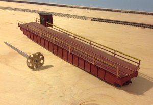
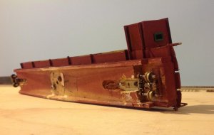
And last, but not least were the trucks. I was kind of scratching my head on this one for a bit. I ended up cutting the basic shape out of hard wood, setting the wheels into place and then putting a board on the outside to hold them there (that will get painted black). I'm not sure I love the design, but we'll see how it works and then go from there.
3567670B-6A04-4FF1-A247-5CB30D300441_zpsbt5scfbp.jpg


And the bridge is complete!
3EC45AFF-363A-4D25-8040-BD766CF82EB2_zpsmi7vh0ws.jpg


If this whole turn table thing does work out in the end, at least I feel that I can be pretty happy with the way the bridge turned out. It will find a home somewhere on the layout, turntable or not.

Now I need to take a break on the project while I order some track for the ring and a few other things. I may put some railings on the bridge, too. We'll see. As for cost so far, I'm up to about $40 so far not including things I already had like paint and stain. Not too bad so far.
 
What do you think is your build time so far? It is really turning out nice and will be something you can be proud of when its finished.
 
Build time? Maybe 5 to 6 hours so far? Some things go quicker than expected (like the thin birch strips to create the verticals, and some things take longer (putting in the horizontal walkway supports ). That does not include design time or the time I spent fussing around with a design program on the computer that I ended up giving up on and going back to good ole pencil and paper.

Going to try and find time to do some more pit work tonight if I can.
 
Your bridge looks pretty nice, but I questioned your building it of balsa wood. I see no reason for it to be lightweight, ...in fact I think it needs to have heft and rigidity.

I chose a different route when I tried building my first one:
Turntable Project

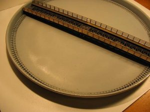
I ended up building my own turntable for my layout. Basically I utilized Atlas bridge components for the rotating center span. The track and walkway portions came from the bases of Atlas (Roco) curved cord bridges, and these were rigidly mounted onto upside down plate girder bridge sections. Made a wonderfull rigid turntable bridge with wooden walks and handrails on the either side.

I glued a spindle from an old 78rpm record player audio turntable onto the underside of this turntable bridge, and this spindle could be pluged into the original record player turntable located under the base pit, and the drive was accomplished with a rubber wheel sprung against the outer rim of the record player turntable.

I experimented with two different 'pit' styles. Both were aluminum pans that just fit the width of the 2 Atlas bridge section end-on-end. One pan was more shallow that the other for a turntable bridge that would consist of just the curved cord sections. The other pan was much deeper to accomodated the thicker turntable bridge with girder bridge sections added.

It would just barely accommodate the longest loco, a Union Pacific BigBoy
Turntable homemade.JPG

I made a second one that I ended up powering with a greatly geared-down motor I purchased from a electronics surplus place that was catalogue mail-order. I'll have to try to remember that link?


And here is a Diamond Scale one I was going to sell, but decided to keep it.
http://www.modelrailroadforums.com/forum/showthread.php?35961-Diamond-Scale-134-turntable-built-up
 
The bridge is looking top notch. Have you figured out what you're going to do for the turntable pit???

To power the turntable, you might look for a used windshield wiper motor from a wrecking yard. I also have a hand crank assembly from a Diamond Scale turntable I'm not using.
 
Last edited by a moderator:
I'll take that hand crank unit off your hands if no one else here wants it. I now believe in the KISS principle


I was actually going to make this turntable on my modified Central Midland layout a hand cranked one, but got sidetracked (and challenged) into powering it.

First it started up as a 'paper pit' with the bridge sitting on it. Then I finally cut out the pit, lowered it as was going to construct laminate plastic pit walls.
paper layout turntable.jpg

steam on display.jpg

IMG_0778.jpg

IMG_0771.jpg

As the previous one, the bridge was constructed of upside down Atlas bridge sections with the curved cord sections glued onto the top
 
Last edited by a moderator:
I'll post a photo of the hand crank when I get a chance. The motorizing unit for the Walthers turntable was a piece of garbage. It ended up in the trash and I installed a hand crank on it. It took a bit of work, but it works so much better than the motor.
 
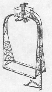
Arch tower

I also purchased 3-4 of the diamond scale arch towers. They were cast metal affairs at the very reasonable price at the time. Too bad Diamond Scale went out of business.
arch tower.jpg
 
Your bridge looks pretty nice, but I questioned your building it of balsa wood. I see no reason for it to be lightweight, ...in fact I think it needs to have heft and rigidity.

Well, I used the Balsa for three reasons, really: #1.) It is 1/4" think so the strength and rigidity shouldn't be a problem. Its also going to sit in a pretty deep pit as the sides are 1 1/2" tall. #2.) I wanted to keep it light weight as the motor I have that I plan to use isn't super powerful (but should be more than enough to turn the bridge. #3.) I had it on hand.


Back
Top