DC wiring question from rookie


Raincoat2

Well-Known Member
Here's a real rookie question regarding DC wiring:

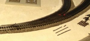
Context: I'm at the beginning of my layout build, still laying track and beginning to do the wiring. The photo below shows my (small) trainyard (hey, I'm limited in space :) ). The mainline is the outside track that comes in from the left and continues on the right-side outside track. There's a turnout in the front of the photo nearest you - it's a Peco electrofrog, and leads into the trainyard. In this building and testing phase, I have wires for the main buss attached at various points to the track, but all are not connected yet - I'm just testing stuff by hooking power through alligator clips to one of the sets of wires, so this part of the layout is not all wired yet.

Problem: When the front picture switch is set for the outside track, the engine runs fine. When I switch to the inner track, the engine stops wherever it is on the outside track.

Is that because I'm using an electrofrog rather than an insulfrog? If so, rather than pull the switch up and replace with an insulfrog, is there a way to wire the electrofrog so power is supplied to all tracks all the time? Or is there another solution? Replace the Peco with an Atlas turnout, perhaps? Some other solution?

Thanks for your help.
Train Yard Mar12-2017.jpg
 
Raincoat2;447347[B said:
Problem: [/B]When the front picture switch is set for the outside track, the engine runs fine. When I switch to the inner track, the engine stops wherever it is on the outside track.

Is that because I'm using an electrofrog rather than an insulfrog? If so, rather than pull the switch up and replace with an insulfrog, is there a way to wire the electrofrog so power is supplied to all tracks all the time? Or is there another solution? Replace the Peco with an Atlas turnout, perhaps? Some other solution?
To truly answer that, we would have to know the whole layout and exactly where the alligator clips were attached while this happens. My guess is that, "yes, this is an electrofrog issue". My guess is that when you switch to the inside track there is another feeder sending power back through the siding track causing a short circuit. If this is the issue you do not have to change turnout but rather just need to add an insulated rail joiner or cut a gap in the two frog rails. Somewhere close to where I put the red dots.

Turnout Gaps.jpg

P.S. It looks like nice trackwork. It is good you are testing before you get it all laid down. That is always one of my first recommendations. Lay a few pieces of track, wire it, test it. Go to next piece.
 
Last edited by a moderator:
Hey, Iron - Thanks for responding. As you can probably see in the photo, I have power wires where the Peco TO connects to the mainline track coming in from the left. I also have wires about halfway down that inside right track (the track that leads to the various TOs of the trainyard). The entire layout is not in a continuous loop yet: the mainline coming in from the left extends another 5 or 6 feet in that direction and ends; the mainline on that right side outside track continues along the back wall another 6 or 8 feet and stops. So there is no complete loop yet. I started building this layout at the most complex part - - the trainyard with all its TOs, knowing (especially as a newbie) I might run into problems. I'm conscious of the basics of wiring - on all track the outside rail is the + rail and the inside rail is the - rail. I have a mixture of Peco and Atlas switches that I was either given or picked up along the way. I thought I had researched electrofrog vs insulfrog types so that I would know what I was doing, but I guess I don't.

Anyway, I attached the alligator clips to the wires at the TO at the front of that photo. The engine would run fine from the left side of the mainline, over the switch, and continued onto the right side outside mainline track. At any time if I threw the TO the engine would stop dead. Not only that, but I couldn't get the engine to run onto the inside track, even if I hooked the alligator clips to wires about halfway down that inside track.

Any suggestions will be helpful. Got to solve this problem before I continue laying track, and I need to learn before I get into other complicated areas.
 
I have power wires where the Peco TO connects to the mainline track coming in from the left. I also have wires about halfway down that inside right track (the track that leads to the various TOs of the trainyard). The entire layout is not in a continuous loop yet
Yup, that will do it. A location near where I showed an insulated joiner on the frog rail of the inside track will take care of your current issue. The insulated joiner on the frog rail of the outside track will solve the future problem when you complete the loop.
 
Last edited by a moderator:
Yup, that will do it. A location near where I showed an insulated joiner on the frog rail of the inside track will take care of your current issue. The insulated joiner on the frog rail of the outside track will solve the future problem when you complete the loop.

Iron - Thanks for this info. I'll work on that this week. Appreciate it very much.
 
Everyone,
here's a follow-up question concerning switches and wiring on my layout. The earlier problem was resolved - Iron Horseman's suggestion on adding insulating rail joiners was correct, and if I had followed the instructions on the Peco packaging, I would have seen that earlier.

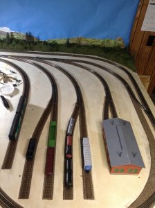
But now, here's a new question. In the photo, you'll see that on the inside track along the back wall I have a series of turnouts. These feed my small freight yard, designated by the various tracks running down to the front of the photo and ending. The train backs into these tracks to drop off/pick up freight cars. There are actually four turnouts in a row, connected directly to each other (because of space limitations). Two are Atlas and two are Peco electrofrogs. I understand now how to wire (and insulate) the rails on an electrofrog. But how do I do that with four switches in a row? Any advice from you experienced folks will be a great help - I'm at this point in the layout and need to wire these so they all work.


Mar26-17(2)FreightYard.jpg
 
But now, here's a new question. In the photo, you'll see that on the inside track along the back wall I have a series of turnouts. These feed my small freight yard, designated by the various tracks running down to the front of the photo and ending. The train backs into these tracks to drop off/pick up freight cars. There are actually four turnouts in a row, connected directly to each other (because of space limitations). Two are Atlas and two are Peco electrofrogs. I understand now how to wire (and insulate) the rails on an electrofrog. But how do I do that with four switches in a row? Any advice from you experienced folks will be a great help - I'm at this point in the layout and need to wire these so they all work.
When the track coming off the turnout is stub ended and has no electrical feeder on it, there is no special wiring needed. The only insulated joiner/gap needed for the whole set would be exactly one for the last electro frog turnout of the set on its frog rail that connects back to the loop. On the other hand, if there are wire power feeds to those tracks the electrofrog turnouts will need two gaps each. One on each frog rail. The Atlas need no special wiring.
 
Last edited by a moderator:
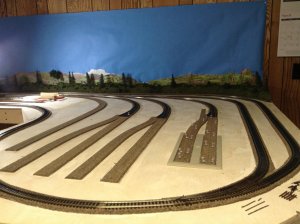
The basic rule for wiring turnouts, regardless of Insulfrog or Electrofrog is always feed from the point end of the turnout. Other than resistance losses, it doesn't really matter how far from the points the wires are connected. The ONLY caveat is that you need to put insulated rail joiner on the frog rail of the turnout leading from the continuous loop. The Peco turnouts will feed power to the particular spur to which the points are thrown. All the rest of the spurs will be dead until the various turnout points are thrown to allow a train to run into one spur. If you move a locomotive into the engine house and throw the turnout against that spur, the spur will be dead and the engine can be stored there until the turnout is thrown to allow the engine to move over the track. In the photo shown throwing the turnout that leads to both engine house against it, will kill both short spurs leading to the house. This is called "power routing". I can't tell from the photo, but if you have a crossover between two continuous loops, you need both rails of the crossover insulated. Hope this helps.
 
Trailrider - Thanks for your comments. I spent most of Saturday working through each section of the freightyard, finding various problems and resolving them. The main problem was that one of the Peco turnouts was bad. I'm a rookie and can't tell if a switch is bad by looking at the underside but that seems to be the only logical explanation. (It's been months since I bought that turnout, and MBKlein has a one-month return policy, so I'll have to bite the bullet on that one, unless I can figure out how to fix the TO - maybe my LHS can help.) Once I figured that out, I removed that turnout and replaced it with an Atlas. I prefer the "action" on the Peco turnouts over the Atlas ones (unless I add remote control to the Atlas TOs, which I haven't done yet). Part of the problem was supplying feeder lines to the spurs, including the engine house. Anyway, by the end of Saturday everything was working fine and I THINK I understand going forward. Again, thanks for responding - your information is useful. In fact, I'm thinking of adding a double crossover further on down the layout, and I'll keep you your comments about crossovers handy when I get to that point.
 
Unrelated issue, but if you moved the switches for the yard tracks to immediately after the lead, you can have longer yard tracks.
 
What do mean by the turnout being bad? Do you have a multimeter? Can you solder feeders to rail?

Leva - Not sure what was wrong with that TO, but even after insulating and wiring appropriately, it still would not operate correctly. Anyway, I've moved the location of the TO and replaced it with a different one.
 
Unrelated issue, but if you moved the switches for the yard tracks to immediately after the lead, you can have longer yard tracks.

Dave - Yeah, I thought of that, too, but the yard tracks are curved, as you can see, and the curved TOs were tricky to work into the space I have.


Back
Top