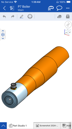
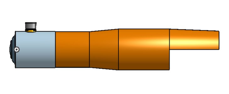
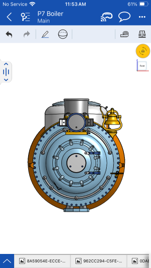
Baltimore&Ohio P7 class, CAD model update: 04/18/24 Boiler start


Okay small update. I have started work last night on the coal bunker and water tank, things are still very rough and will need a lot more work to get done. Also please note, neither of these assemblies are in the correct location to eachother or the tender frame components I’ve already modeled. Once I’ve got more things modeled, I will position everything correctly.
IMG_1997.jpeg
 
From what I remember the harbor freight lathe was not terrible, I just had crummy tools and not a lot of material to practice on when I had it. I’m not sure if they still offer it. I graduated ten years ago now, the class I took was through a trade school, they would allow high school students in at 10th grade if I remember correctly and still cost a bit of money, mainly for materials etc. I don’t think the cost was to terrible, I think it was around 1500 a semester but I could be wrong about that lol. They really should have more classes for the trades imho. I mean hell, someone could put themselves into hundreds of thousands in debt for a degree that likely won’t get them anywhere, or they could spend a very small fraction of that, learn a trade and likely have a good paying job before they even graduate
I did get the knifes for my lathe in Harbor Freight, as the lathe did not include those. They're pretty good so far, although i've been using only one for the most part.
Yeah, the trade schools are it, if someone wants to do good. The regular college degrees are nothing but a scam to put and keep thousands of young people in debt. Skills like you have are i short supply and before i bit the bullet and invested in my lathe, i checked a few machine shops for pricing on the tires i wanted. I've made scale drawings and was quoted $300 and up just for a set of 10 tires. So i said "screw it, time to teach myself something new".
 
They have some pretty decent tooling at harbor freight for sure. I can’t remember if the lathe from there included bits or not as that’s so long ago now lol.
I agree, trade schools are really the answer. You can get trained into a skill that not many other people possess or have interest in, have a better chance of getting a job that won’t be automated so easily in the future and be guaranteed a steady source of income for as long as you wish to work in that field.
I do not currently work in the machining field in manufacturing (I work at a tobacco store) but I do plan on getting a 3d print farm up and running. Long term I’d like to offer 3d modeling/printing/machining/casting etc. I’ve already started to do some 3d modeling for the customer I mentioned before, so I’m making some progress on the business side that feels pretty good to accomplish.
And hell I would say the exact same thing you did, it’s always fun to learn a new skill. Plus now that you have a lathe, you could do odd jobs for people to help recoup the cost of the equipment and tooling
 
Hey guy, just dropping in to give a brief update.
I have been working on the tender water tank for the p7 for the last few days and have finally gotten this portion of the tender nearly finished. Ironically this is one of the larger assemblies I’ve worked on so far. I’ve attached a couple of photos to show how everything looks right now.
the first photo, fairly simple and straight forward, this view shows the main tank body, second image shows the internal structure. There’s quite a few tank baffles running down the center line and 4 sets of two running towards the back.
IMG_2024.jpeg
IMG_2025.jpeg

I’ll be back in a few days once I’ve got more things sorted out. My next step is likely going to be positioning this assembly onto the tender chassis I posted previously.
Hope you are all doing well, I look forward to talking with you guys more 😊
 
Got a small update for you guys tonight. I won’t be working on the model for a few days as I’ve run into a problem that’s made working impossible. The program I use on my phone needs an update, but apple has made it so you need to have a minimum amount on your credit card in order to install an update that doesn’t cost anything. Since I won’t have any money on that card for a few days I cannot work anymore unfortunately.
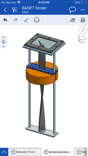
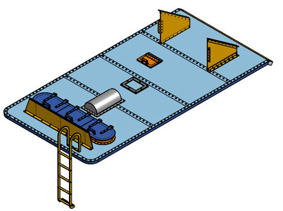
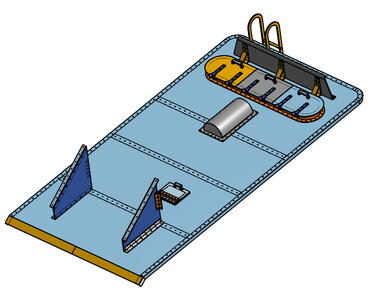
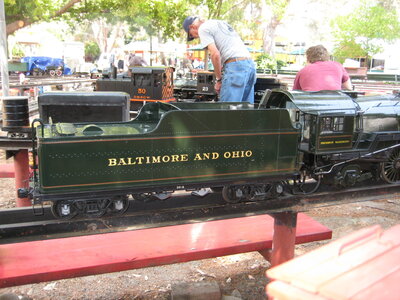
Anyway, now it’s time for the update on the cad model. I started modeling the water gauge that sits inside the water tank in my last post. I’ve got that modeled completely now but I needed to start working on the top of the tender in order to figure out the relative position of the water gauge assembly inside the water tank. The images I’ve attached show the water gauge assembly, the top of the tender. The tender top is nearly complete, I need to rotate the water deflector (shown in grey) 90* and possibly modify the profile a bit to fit correctly. I’ve also attached a photo of the 1:12 live steam tender to show what I mean with that part. I am also working on pulling all of the tender components into one part studio so I can start seeing how everything looks, and most importantly the position of some new smaller components I have yet to model.
That’s it for now, hope your all doing wellIMG_2085.pngIMG_2084.jpegIMG_2061.jpegIMG_1179.jpeg
Edit: ignore the dark grey part in the second image. That is there to help reference the hole location for the water gauge
 
Aright, it’s been about 3 weeks since my last post, sorry for the delay. I have not done very much modeling at all (except an hour last night) My family and I moved to a new house so we’ve been busy getting settled, I’m still waiting for taxes to hit so I can order the remaining parts I want to get for my printer rebuild, I am going to be doing some work for a friends company which will be providing a computer. Here’s what I did get done last night.
I have gotten to a point in the tenders construction where I really need to start modeling the outer shell of the tender, but the fun part that I’ve been dealing with is a lack of dimensions for the sides of the tender or the back head. I know most of the basic dimensions can be guesstimated from the parts relation to its mating surface. I have started modeling the blackhead of the tender as well as the cross bars that help stiffen the back head up. I’ve attached a few photos showing a general view of all tender components minus trucks and a close up of the back head. The back head of the tender, as designed has a material thickness of .012”. Because of the thinness of this part, you can see the supporting crossbars behind the modeled part. When I go to actually optimize all the parts for printing, I will be setting a minimum part thickness to help make things a bit more strong. I’m also planning on using heat set inserts for a more solid connection with my mounting hardware.
IMG_2243.jpeg
IMG_2241.png
IMG_2242.png
 
Okay, I’ve done more work to the coal bunker and I’m getting closer to a more finished tender thankfully. I’m getting really excited to start working on the rest of the locomotive itself. I still have to print off all the new drawings that I’ve been working with in regards to the tender. I’m the photos I am attaching below, I have pulled the entire locomotive, minus the Nathan lubricator. I have also started to go through all the components in this reference part studio and merge components together to cut down on my total part count. I can’t recall the total number of modeled components at this point but I would estimate the total part count to be around the 500 amount.
IMG_2281.jpeg
IMG_2282.jpegIMG_2283.jpeg
IMG_2284.jpeg
IMG_2285.jpeg
IMG_2286.jpeg
IMG_2287.jpeg

I am also going to be getting a laptop sometime in the next week and will continue modeling on that instead of using my iPhone 8. I have also ordered the remaining components I need to rebuild my Ender 5 printer. If all goes well I might be able to start printing some of the parts in the next month. I am considering picking up a resin printer to help with some of the smaller more detail oriented components. The majority of the parts will be printed on the Ender 5, the remaining parts that are two large to print on this machine I will print on either a belt fed printer or on a Elegoo Orange storm giga which has a print volume large enough to print the locomotives frames with are nearly 31” long. Anyway. That’s all for now. I hope you are all doing well
 
IMG_2313.jpeg
IMG_2314.jpeg
IMG_2327.jpeg
IMG_2328.jpeg
Small update on the tender today guys. I have started to work out the supporting inner stricter that the physical tender body is mounted to. I roughed out a rough skeleton that wraps fully around the tender and started to figure out the placement of the Stoker engine access door which sits on the front left side of the tender body. I have modeled the door and adjusted the runners to the correct length (visually as no dimension is called out in the print) and added in some extra bracing behind the door. There are a few other things I started adding rivet holes to the assembly, as well as splitting the side panels to create a riveted seam which I will work on next.
 
Alright I’m back, I’ve been pretty busy working on some other things this week but I have managed to make some more progress on the tender for the P7. This week I’ve been focusing on finishing up the coal bunker as well as detailing the front of the tender itself.
I started by detailing the rest of the coal bunker. I had already gotten the main profile of the bottom plate as well as the sides of the tender figure out so I worked on finishing the bunker walls. After this was complete I moved on to the doors, hinges and latches for the tool boxes on the front of the tender. The exact position of these doors is not called out in any of the drawings I have looked at so I have done my best to line them up as close as I can with the original drawings I am working from. Once this was figured out I could finally move onto the piece that will eventually turn into the tender footplate.
I’d like to start modeling the tender water pump but don’t have any drawings for one. Can anyone point me in the direction of the pump shown in the last photo? I’d like to recreate it in cad if drawings are available.
IMG_2397.png
IMG_2399.png
IMG_2400.png
IMG_2398.png
IMG_2401.jpeg
 
Hello everyone, small update but pretty good news. I have purchased a laptop from a friend of mine, it needs a new copy of windows and a factory reset, once that is finished I will be able to power up my 3d printer and finish getting the 3d printer rebuild complete. I will also continue modeling on the laptop instead of using my old iPhone.
I have been working a lot on the less fun side of the project for the last couple of weeks. What I mean is, I am making a complete Bill of materials and writing a build manual so other people can work on this project if they feel ambitious enough.
I have written down every single drawing, and every single part called out in the drawings. All drawings have been assigned a reference number as well. So far this model has a total drawing/parts count of
IMG_2520.jpeg

As for the instruction manual I am loosely following the build steps laid out in this kit right here. I say loosely mainly because the P7 is going to have substantially more parts, so I’m mainly just following the basic build steps with extras added in for all the various detail parts. At the same time I have started a new Project folder in my cad program and I am starting to prepare parts to print. I am going to be building the 1:32 scale version of the p7 as I write the manual. Anyway, that’s about all I have for you guys today. Thank you so much for reading
 
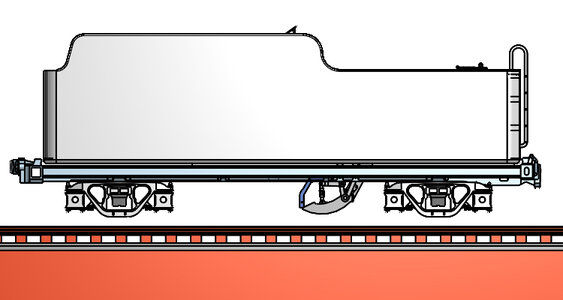
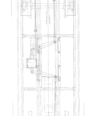
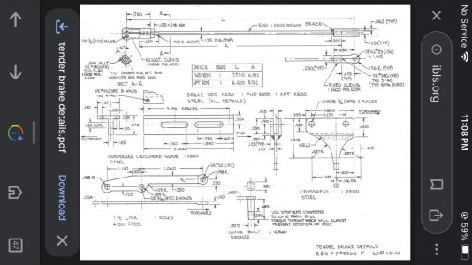
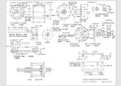
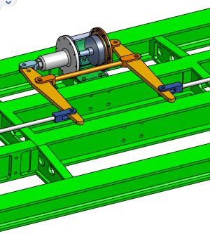
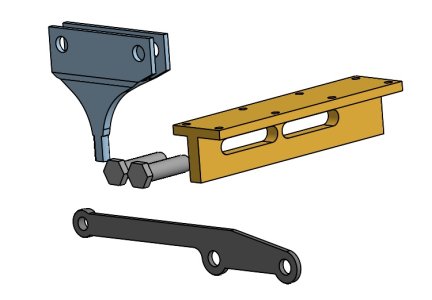
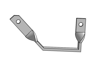
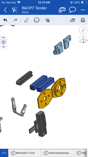
Hey guys, another quick update for all. I have continued working on the tender for the locomotive, I have finished nearly all other parts in the tender and have started adding some more detail bits, mainly the brake rigging. I’ve gotten a majority of the parts modeled in the last couple days. I have also started moving all parts to the correct relative position so I will be able to import all the parts from this studio into my assembly studio with minimal effort in positioning. I have attached a few photos showing the drawings I am working from, including a layout view depicting the locations of all parts. I have also added a few photos of the parts that I have modeled/ positioned, as well as a bunch of parts I still have to figure out the position of. IMG_2612.jpegIMG_2603.jpegIMG_2589.jpegIMG_2608.jpegIMG_2609.jpegIMG_2610.jpegIMG_2611.png
 
Hello everyone, I have a relatively quick update for everyone tonight. I have gotten my laptop up and running, and I have continued modeling the P7 on the computer instead of using an iPhone. The user interface is a little bit different than with the mobile device. I am still getting used to it, but I am enjoying the computer a lot more than using a phone to do this sort of modeling.
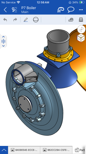
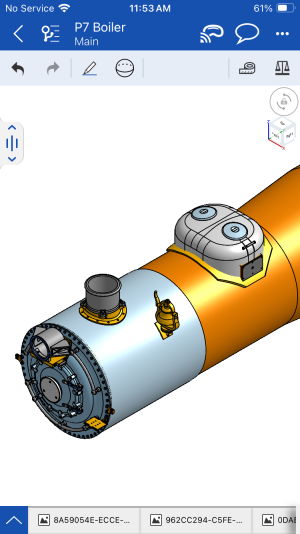
I have started to work on the boiler for the locomotive so far I have roughed out the main boiler shell and smoke box as well as Smokebox door some various other components to hold the smoke box on and the stack/stack base has also been rough modeled.
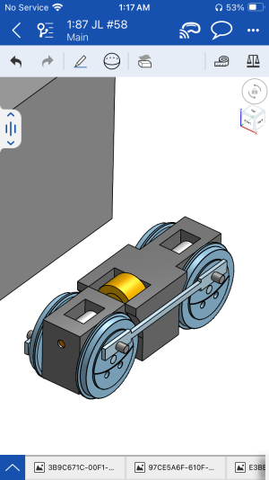
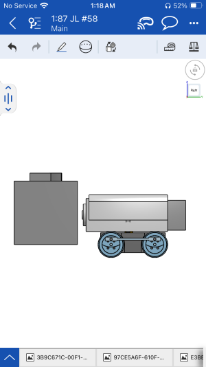
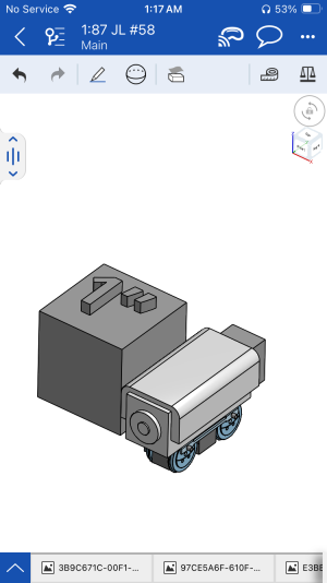
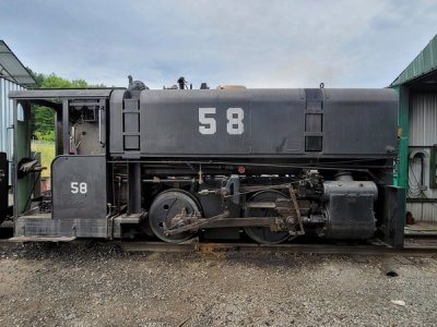
I also also have started working on a very, very small side project. I’ll attach a photo of it as well as a reference photo for what I am going for if anyone else is interested in seeing this build further I can start a separate thread for it. Long story short it is a 187 scale model of a 2 foot narrow gauge locomotive. It’ll be running on the scale track which gives a scale track gauge of just about 22 inches. This will give a much more realistic gauge in 187 for 2 foot instead of using the normal end scaler 9 mm gauge. IMG_2829.pngIMG_2830.jpeg
Here are a few photos of the 187 scale 2 foot narrow gauge Jones and Laughlin number 58 locomotive. I placed a 1 inch cube next to the model to show how small it is. The 1 inch text on top of the cube is only 1/8 of an inch tall to help give a sense of scale. This has been an engineering challenge mainly because the components are so small and they are at almost minimum wall thickness for 3-D printing. If anyone is interested in following this build, let me know. I will start a build thread on it once I get more parts designed and on hand.
IMG_2799.pngIMG_2801.pngIMG_2800.pngIMG_2793.jpeg
 
Got another small update tonight guys, I’ve been working on detailing more of the smoke box and have added in the headlight/bracket, number plate, and the smoke box door lugs. I still have some tweaking to get things 100% but here is how the smoke box door is shaping up. IMG_2838.png
 
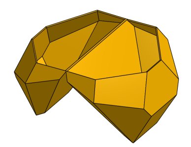
Alright, I’ve added some more parts and have the smoke box door/front face almost finished. There are still some small changes and things I still need to add. I’ve also started work on the sand dome. I have the profiles roughed out, as well as the sand box that goes in the sand dome. This was a little bit of a challenge to model mainly due to it being made from a flat sheet of steel and bent into place. The drawings include the flat pattern from that part and give bend angles but no dimensions, the second drawing shows the complete sand box with some main dimensions that I used to tweak the model and make everything the way it should be. Here are a few photos showing the details added to the smoke box, sand dome and sand box. IMG_2861.pngIMG_2862.pngIMG_2860.jpeg


Back
Top